LED Package with Slanting Structure and Method of the Same

a technology of slanting structure and led package, which is applied in the direction of solid-state devices, electric devices, basic electric elements, etc., can solve the problems of inability to meet the demand of producing smaller chips with high-density elements on the chip, the package is too thick, and the lead frame package becomes more complicated. , to achieve the effect of improving efficiency and scaling down the size of the devi

Inactive Publication Date: 2015-04-09
KING DRAGON INT
View PDF6 Cites 0 Cited by
  • Summary
  • Abstract
  • Description
  • Claims
  • Application Information

AI Technical Summary

Benefits of technology

[0006]An object of the present invention is to provide a LED package with slanting structure. The present invention provides a LED structure with P, N type through holes from the top surface to lower surface, thereby improving the efficiency and scale down the size of the device.
[0007]Another object of the present invention is to provide a convenient, cost-effective method for manufacturing a LED package (chip assembly).

Problems solved by technology

As a semiconductor become more complicated, the traditional package technique, for example lead frame package, flex package, rigid package technique, can't meet the demand of producing smaller chip with high density elements on the chip.
Due to the manufacturing technology and material requirements, packages having built-up layers often include a number of degassing holes in the metal layers.
However, the package is too thick and structure is also too complicated.

Method used


Image

  • LED Package with Slanting Structure and Method of the Same
  • LED Package with Slanting Structure and Method of the Same
  • LED Package with Slanting Structure and Method of the Same

Examples


Embodiment Construction

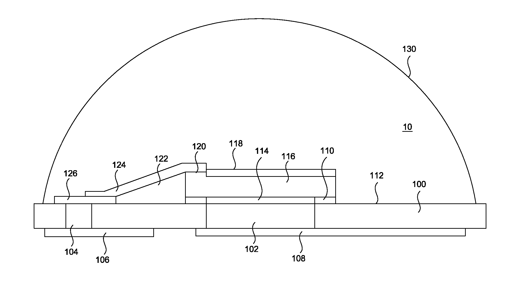
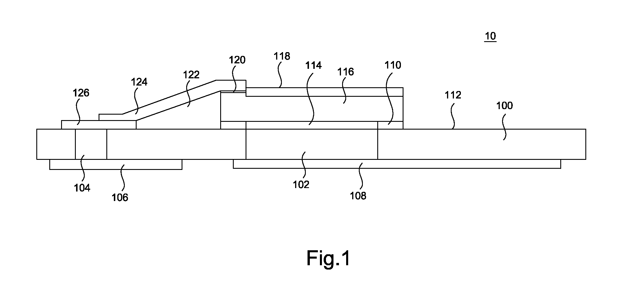
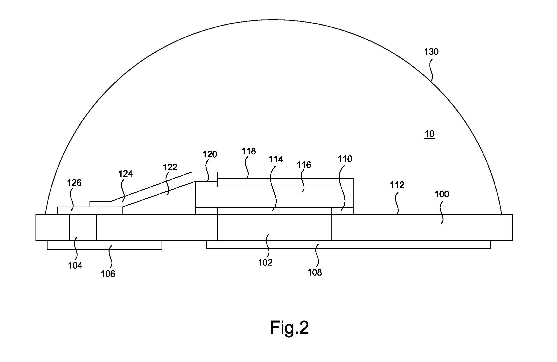
[0013]The invention will now be described in greater detail with preferred embodiments of the invention and illustrations attached. Nevertheless, it should be recognized that the preferred embodiments of the invention is only for illustrating. Besides the preferred embodiment mentioned here, present invention can be practiced in a wide range of other embodiments besides those explicitly described, and the scope of the present invention is expressly not limited expect as specified in the accompanying Claims. The present invention discloses a LED package assembly which includes LED die, conductive trace and metal inter-connecting as shown in FIG. 1. The invention concept also can be applied to the IC packaging, especially for the power device.

[0014]FIG. 1 is cross-sectional view of a LED package 10 having a substrate 100 with predetermined through-holes 102 and 104 formed therein. The substrate 100 could be a metal, glass, ceramic, silicon, plastic, BT, FR4, FR5 or PI etc. The thickne...


PUM


Abstract

A method for forming LED package comprises providing a substrate with a first conductive type through-hole and a second conductive type through-hole through the substrate. A reflective layer is formed on an upper surface of the substrate. A LED die is provided with a first conductive type pad and a second conductive type pad formed on a lower surface and an upper surface of the LED die, respectively. The LED die is adhered on the substrate. A slanting structure of dielectric layer is formed adjacent at least one side of the LED die for carrying conductive traces. A re-distribution layer conductive trace is formed on upper surface of the slanting structure to offer path between the second conductive type pad and the conductive type through-hole.

Description

FIELD OF THE INVENTION[0001]This invention relates to a LED package, and more particularly to LED package with slanting structure adjacent to the die.DESCRIPTION OF THE PRIOR ART[0002]High performance integrated circuit (IC) packages are well known in the art. Improvements in IC packages are driven by industry demands for increased thermal and electrical performance and decreased size and cost of manufacture. In the field of LED devices, it is required to be package as the IC device. The die density is increased and the device dimension is reduced, continuously. The demand for the packaging techniques in such high density devices is also increased to fit the situation mentioned above. Conventionally, in the flip-chip attachment method, an array of solder bumps is formed on the surface of the die. The formation of the solder bumps may be carried out by using a solder composite material through a solder mask for producing a desired pattern of solder bumps. The function of chip package...

Claims


Application Information

Patent Timeline
Patent Type & Authority Applications(United States)
IPC IPC(8): H01L33/62H01L33/60
CPCH01L33/60H01L33/62H01L33/005H01L33/48H01L2933/0033H01L2933/0066H01L33/486H01L33/54H01L24/24H01L2224/24226H01L2224/24246H01L2224/32225H01L2224/32245H01L2224/73267H01L2924/12041H01L2224/24105H01L2224/24998H01L2924/351H01L2924/12042H01L2924/00
Inventor YANG, WEN KUN
Owner KING DRAGON INT
Why Eureka
Try Eureka