
Oxygen concentrator for mechanical ventilation

a concentrator and oxygen technology, applied in the field of concentrators, can solve the problems of limiting usability, requiring higher pressure, and certain types of delivery devices

Active Publication Date: 2015-04-23
INOGEN INC
View PDF10 Cites 11 Cited by
  • Summary
  • Abstract
  • Description
  • Claims
  • Application Information

AI Technical Summary

Benefits of technology

The patent describes a system for delivering oxygen to users at different pressures for different types of delivery devices. The system includes an oxygen concentrator, a pressure amplifier, a product tank, and a user connection switch. The system allows users to choose low pressure or high pressure oxygen delivery devices depending on their preferences. The technical effect of this invention is that users can have access to pressurized oxygen at different levels of pressure and can choose their preferred delivery device accordingly.

Problems solved by technology

One drawback of conventional oxygen concentrators is that certain types of delivery devices, such as smaller varieties of nasal cannula, require higher pressures in order to ensure effective oxygen delivery to the user.
Under normal operating conditions, a conventional oxygen concentrator cannot provide high pressures, and so delivery devices designed for those high pressures cannot be used with conventional oxygen concentrators, thereby limiting usability.
However, this technique is generally problematic because increasing pump speed may cause undue mechanical fatigue, thereby reducing the overall lifetime of the oxygen concentrator.
In addition, increasing pump speed generally increases power consumption.
With portable oxygen concentrators that rely on battery power, an increase in power consumption may result in a corresponding increase in battery size, which reduces portability, or a decrease in operating time, which limits usability.

Method used


Image

  • Oxygen concentrator for mechanical ventilation
  • Oxygen concentrator for mechanical ventilation
  • Oxygen concentrator for mechanical ventilation

Examples


Embodiment Construction

[0018]In the following description, numerous specific details are set forth to provide a more thorough understanding of the present invention. However, it will be apparent to one of skill in the art that the present invention may be practiced without one or more of these specific details. In other instances, well-known features have not been described in order to avoid obscuring the present invention.

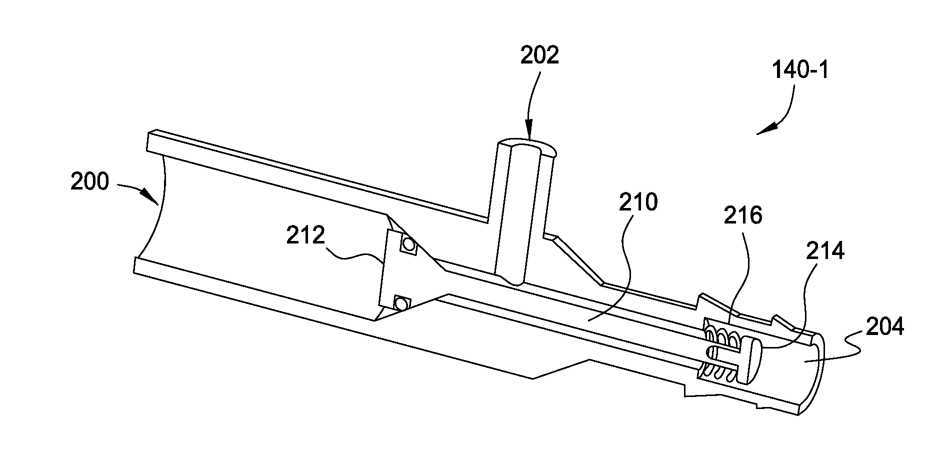
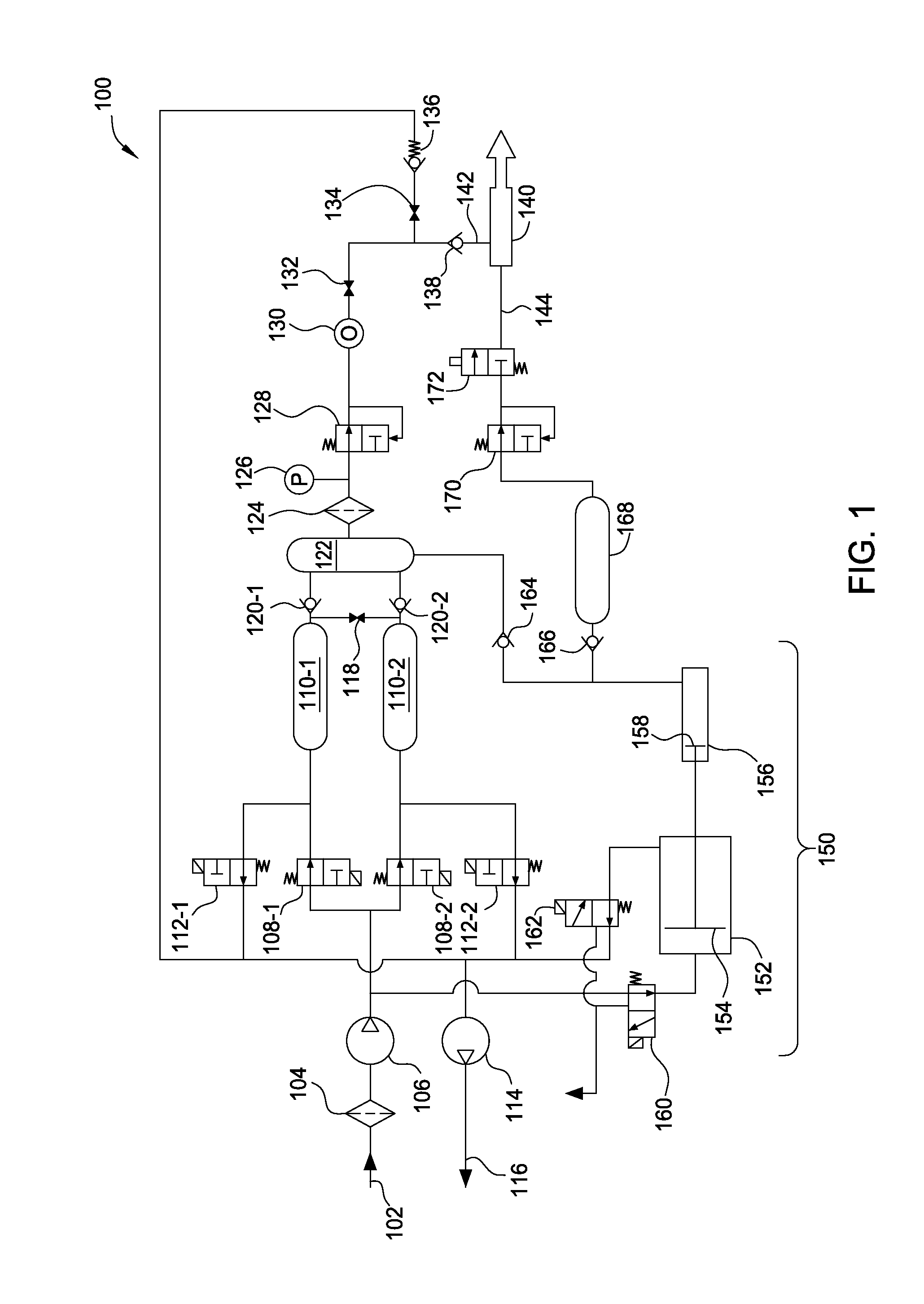
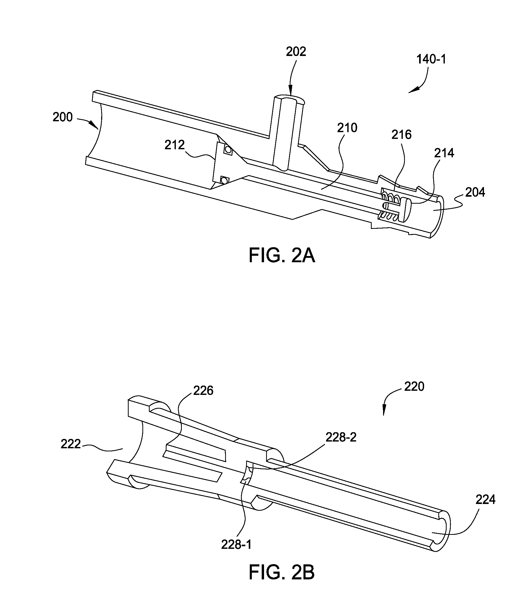
[0019]As described in greater detail herein, an oxygen concentrator is configured to provide oxygen to users at either lower pressures or higher pressures. When providing low pressure oxygen, the disclosed oxygen concentrator may be used with a conventional, low pressure oxygen delivery device, such as an oxygen cannula or mask, that is configured to deliver oxygen at approximate source pressures of 5 psig to 8 psig. When providing high pressure oxygen, the disclosed oxygen concentrator may be used with a high pressure oxygen delivery device, such as a low profile nasal cannula, that is...


PUM

PropertyMeasurementUnit
pressureaaaaaaaaaa
pressuresaaaaaaaaaa
pressuresaaaaaaaaaa

Abstract

An oxygen concentrator is configured to provide oxygen at either lower pressures or higher pressures. When providing low pressure oxygen, the disclosed oxygen concentrator may be used with a conventional, low pressure oxygen delivery device, such as an oxygen cannula or mask, that is configured to deliver oxygen at approximate source pressures of 5 psig to 8 psig. When providing high pressure oxygen, the disclosed oxygen concentrator may be used with a high pressure oxygen delivery device, such as a low profile nasal cannula, that is configured to deliver oxygen at higher pressures. The disclosed oxygen concentrator is configured to automatically select whether low pressure oxygen or high pressure oxygen should be output to the user based on the type of connector used to couple a delivery device thereto, or based on characteristics of the delivery device itself.

Description

CROSS-REFERENCE TO RELATED APPLICATIONS[0001]This application claims the priority benefit of the U.S. provisional patent application titled, “Oxygen Concentrator for Mechanical Ventilation,” filed on Oct. 18, 2013 and having Ser. No. 61 / 893,022. The subject matter of this related application is hereby incorporated herein by reference.BACKGROUND OF THE INVENTION[0002]1. Field of the Invention[0003]Embodiments of the present invention relate generally to concentrators, and, more specifically, to an oxygen concentrator for mechanical ventilation.[0004]2. Description of the Related Art[0005]An oxygen concentrator is a mechanical device that filters nitrogen out of atmospheric air to produce fluid with a higher concentration of oxygen. The oxygen is delivered to a user via a delivery device, such as an oxygen mask or nasal cannula. Conventional oxygen concentrators output oxygen to users at pressures between 5 and 8 pounds per square inch gage (psig). Generally, during operation, such ox...

Claims


Application Information

Patent Timeline
Patent Type & Authority Applications(United States)
IPC IPC(8): A61M16/10A61M16/20A61M16/06A61M16/08B01D53/04A61M16/00
CPCB01D2253/108A61M16/105B01D2256/12B01D2259/402B01D2259/4533A61M2016/0027A61M2016/1025A61M2202/0208A61M2205/3334A61M2205/3327A61M2202/0266A61M2205/75A61M16/101B01D53/0446A61M16/0003A61M16/0063A61M16/0672A61M16/0816A61M16/1005A61M16/208B01D2257/40A61M16/209B01D53/047B01D2257/102
Inventor ALLUM, TODD
Owner INOGEN INC
Learn More