Fast generation of elements with individually patterned anisotropy

Active Publication Date: 2015-04-23
ROLIC AG
View PDF18 Cites 15 Cited by
  • Summary
  • Abstract
  • Description
  • Claims
  • Application Information

AI Technical Summary

Benefits of technology

[0005]An object of the present invention is to provide an apparatus which allows producing elements with individually patterned anisotropic properties,

Problems solved by technology

However, such a method is hardly app

Method used


Image

  • Fast generation of elements with individually patterned anisotropy
  • Fast generation of elements with individually patterned anisotropy
  • Fast generation of elements with individually patterned anisotropy

Examples


Example

Application Example 1

Batch Processing

[0146]A solution S(PA) is prepared by dissolving 3 wt % of the photo-alignable polymer P in a solvent mixture consisting of 97 wt % MEK and 3 wt % CHN.

The absorption coefficient α(390 nm) has been determined as 90500 [1 / cm].

[0147]A LCP-solution S1(LCP) is prepared by dissolving 15% by weight of mixture MLCP in a solvent mixture consisting of 97 wt % MEK and 3 wt % CHN.

[0148]Mixture MLCP comprises polymerizable liquid crystals and consists of:[0149]76.4% LC1[0150]14.3% LC2[0151]4.8% LC3[0152]4% Irgacure 907[0153]0.5% BHT

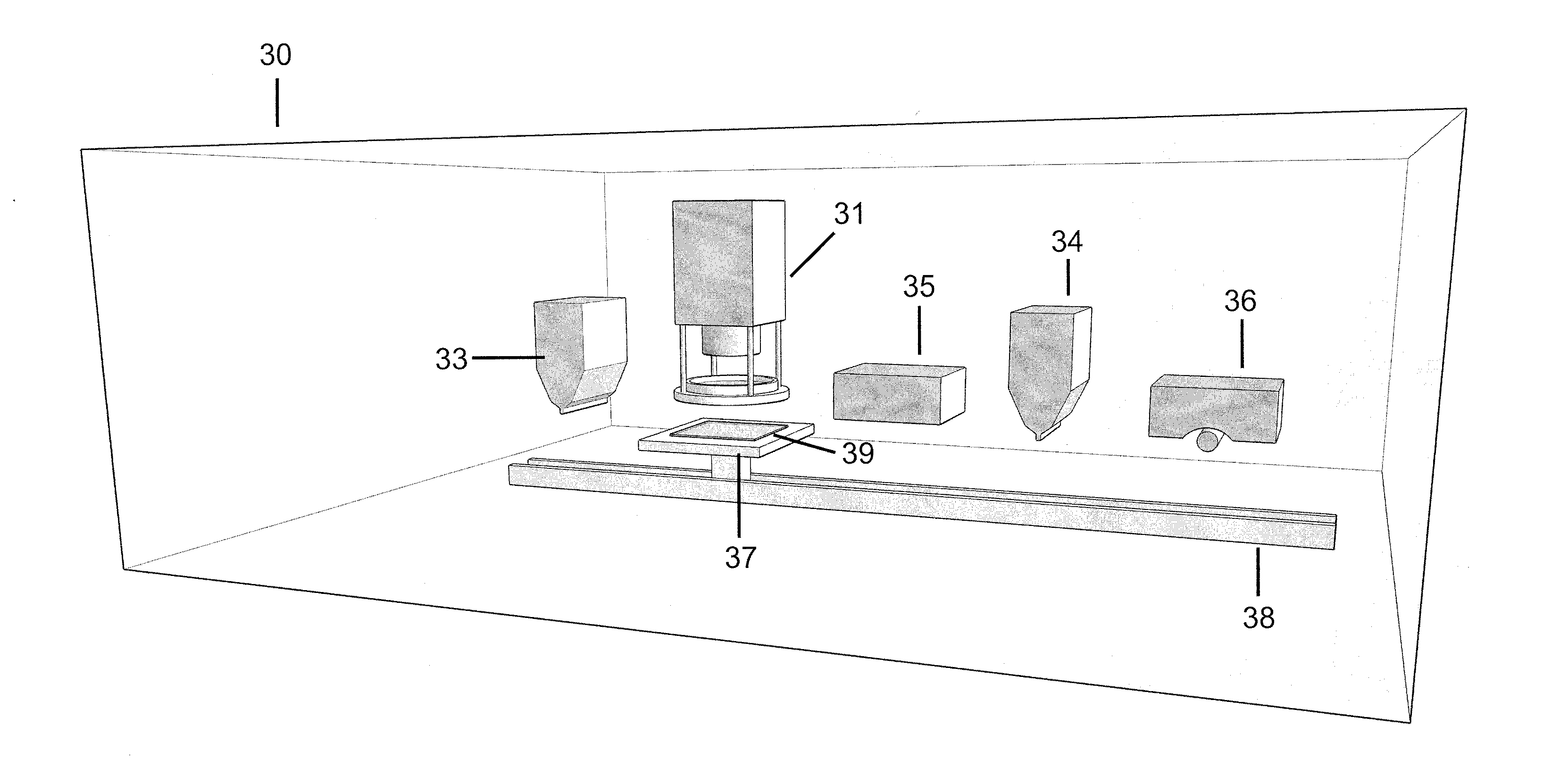
[0154]The apparatus for processing according to this application example comprises[0155]a first ink jet head comprising 16 nozzles of 18 μm diameter (REA Jet). The first ink jet head provides the solution S(PA),[0156]a 150 W IR lamp as a heater,[0157]an SLM exposure unit, which comprises a 0.7 inch diagonal DMD with 768×1024 micro mirrors (Texas Instruments) and a high power LED as a light source, which emits light at 390 nm. The e...

Example

Application Example 2

Reel to Reel Processing

[0166]This example describes reel to reel processing, demonstrating the manufacture of individualized highly resolved images in a continuous manufacturing process.

[0167]A LCP-solution S2(LCP) is prepared by dissolving 30% by weight of mixture MLCP in a solvent mixture consisting of 97 wt % MEK and 3 wt % CHN.

[0168]The apparatus used in this example is a modified version of that of FIG. 6, since it is not equipped with the second coating unit 77, the second heating unit 79 and the curing unit 80. In addition to the embodiment of FIG. 6, the apparatus is equipped with a corona treating unit, positioned between the support 74 and the coating unit 76. The coating unit is of the type reverse kiss coating.

[0169]The same type of exposure unit 71 is used as described in application example 1 above. A 23 μm thick aluminised PET foil is used as a substrate, which continuously moves at a web speed of 5 m / min from support 74 to support 75. Accordingly...

Example

Application Example 3

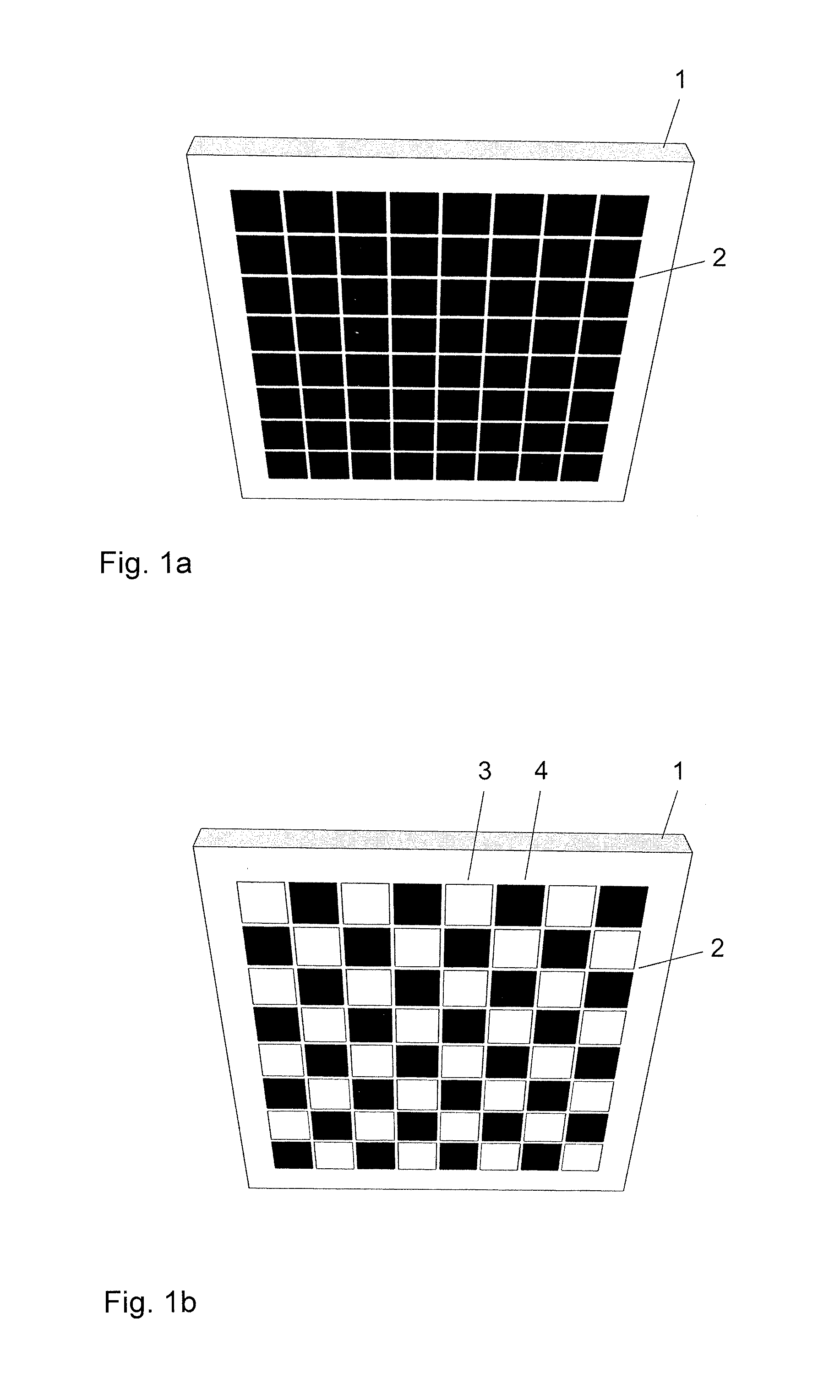
[0173]The same apparatus is used as described in application example 1. As in application example 1, an aluminised PET foil is coated with a layer of S(PA) and dried under the IR lamp. The sample is then moved under the SLM exposure unit. This time the image to be projected consists of 9 binary sub-images, as shown in FIG. 8. Each sub-image comprises 2 bright pixel-columns, while the remaining area is dark. The positions of the bright columns change from sub-image to sub-image. The set of sub-images is designed in such a way that the bright areas are not overlapping and that the sequential exposure of the whole set of images exposes the complete projection area. Furthermore the azimuthal direction of polarization is changed from exposure to exposure by turning the polarizer by 15° after each exposure as indicated by the arrows in FIG. 8.

[0174]After this multiple exposure, an LCP layer is coated on top the LCMO layer and dried and cured as described in applicatio...


PUM


Abstract

The present invention relates to an apparatus which allows producing elements with individually patterned anisotropic properties, where the pattern may vary from element to element. An apparatus according to the invention comprises a support for a substrate and an exposure unit for providing spatially modulated aligning light with a first polarization plane, wherein the exposure unit contains a light source, a spatial light modulator, which can be controlled electronically, for example by a computer, and a projection lens. The present invention furthermore relates to a method for fast production of elements with individually patterned anisotropic properties using such an apparatus.

Description

TECHNICAL FIELD[0001]The invention relates to methods and apparatus for fast production of elements with individually patterned anisotropic properties.BACKGROUND OF THE INVENTION[0002]Elements with patterned anisotropic properties are, for example, known as optical elements, which include a layer comprising polymerized or cross-linked liquid crystals with locally different optical axes directions. Such layers are, for example, prepared by applying cross-linkable liquid crystal materials on top of an alignment layer exhibiting locally different alignment directions. The liquid crystal material adopts the local alignment direction of the underlying alignment layer and is then cross-linked to fix the orientation.[0003]An alignment layer with locally different alignment directions can easily be prepared by the photo-alignment technique, where a layer of a material, which is sensitive to the polarization of light, is exposed to linearly polarized light. Patterned alignment is achieved by...

Claims


Application Information

Patent Timeline
IPC IPC(8): G03F7/20
CPCG03F7/70191B29D11/00644G02B5/3025G02B5/3083G02B27/286G02F1/1303G02F2203/12B42D25/364G03F1/00
Inventor SCHMITT, KLAUSSEIBERLE, HUBERT
Owner ROLIC AG
Why Eureka
Try Eureka