
Composite Optical Materials for Mechanical Deformation

Inactive Publication Date: 2015-04-23
CAMBRIDGE ENTERPRISE LTD +1
View PDF9 Cites 37 Cited by
  • Summary
  • Abstract
  • Description
  • Claims
  • Application Information

AI Technical Summary

Benefits of technology

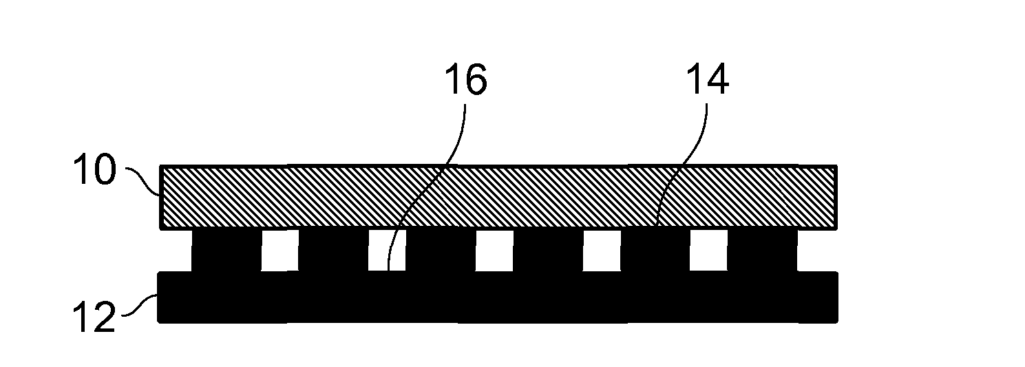
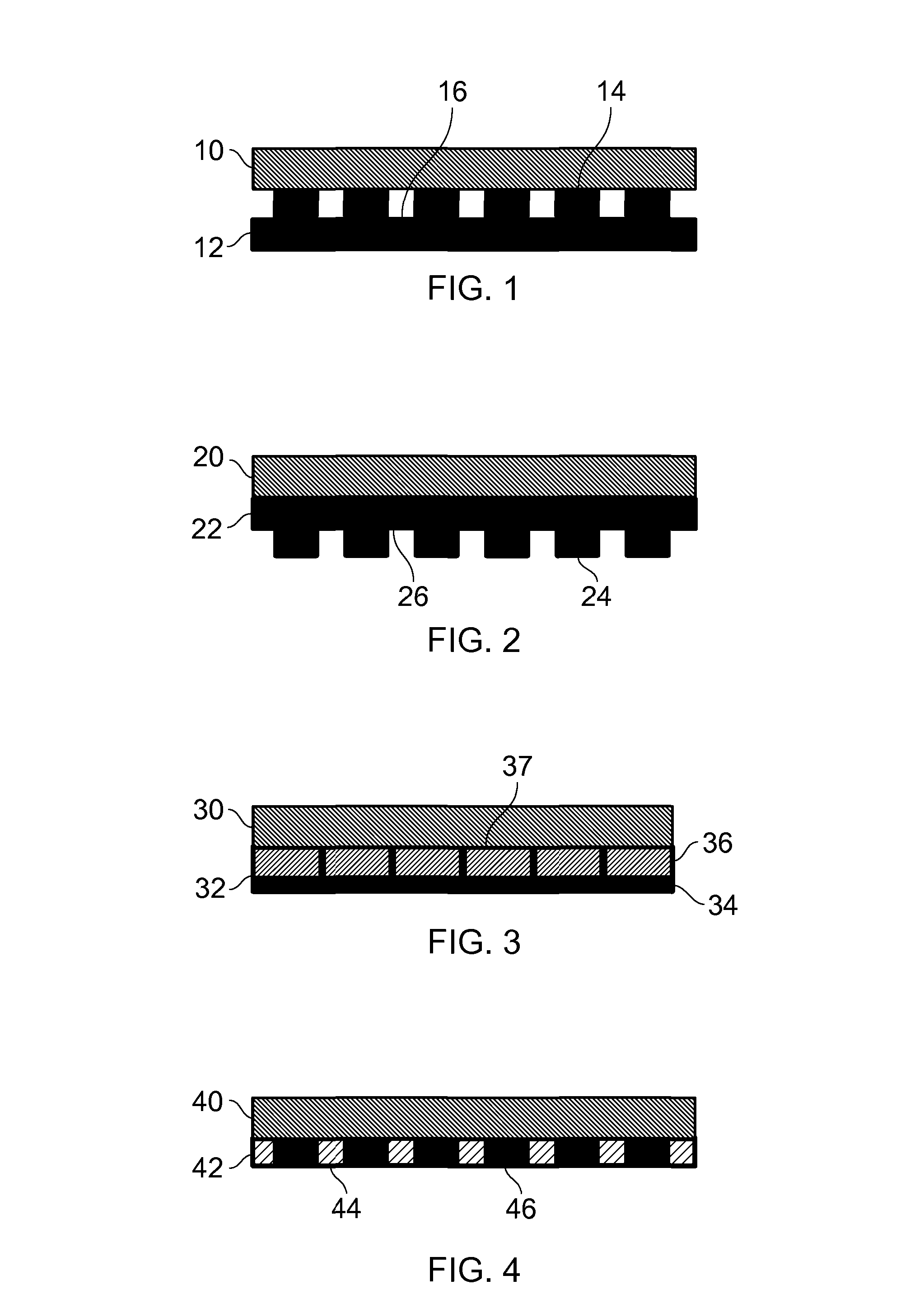
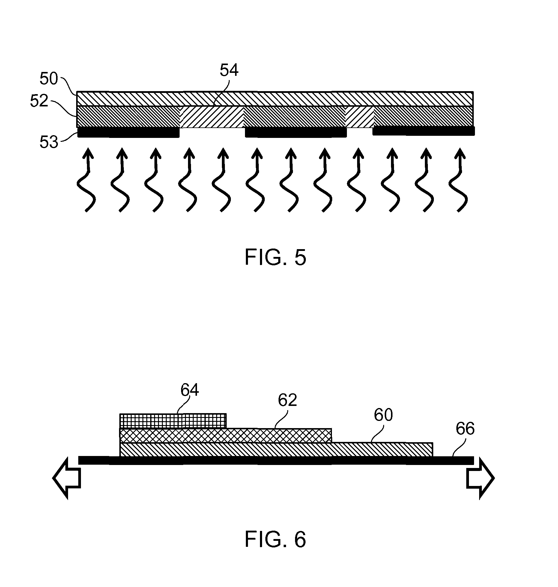
The patent describes a method for making a composite optical device by deforming a layer of material on a substrate. The substrate is made stiffer at different locations, so when the device is deformed, the layer is deformed to different extents at different locations. This results in a change in the device's color response when it is mechanically deformed. The method also includes a technique for making the device by injection molding, where the substrate is allowed to cool before being removed from the mold. This helps to improve the quality of the finished device.

Problems solved by technology

Furthermore, it is considered that typically the maximum stiffness that can be achieved in the polymer opal is limited.
If over-crosslinked, the opal becomes brittle and can crack, losing flexibility and durability.
In the opinion of the inventors, one major drawback of the approach in EP-B-2054241 is that the opal film must provide not only the non-optical properties like mechanical strength and durability but also the optical properties.
This makes it very difficult to adjust the film to meet requirements for certain applications because it is typically of importance for most applications that the colour should not be impaired.
The inventors consider that it is not possible to change e.g. the mechanical strength by a variation of the chemical composition without considering the impact on the process of self-assembly or on the refractive index contrast of the polymer opal film.

Method used


Image

  • Composite Optical Materials for Mechanical Deformation
  • Composite Optical Materials for Mechanical Deformation
  • Composite Optical Materials for Mechanical Deformation

Examples


Embodiment Construction

[0088]The entire content of each the documents referred to in any section of this disclosure is hereby incorporated by reference.

[0089]The rubber-like opal films disclosed in U.S. Pat. No. 6,337,131 (equivalent to EP-A-955323) and US 2004 / 0253443 (equivalent to WO03025035 and EP-B-1425322) were found to be suitable for use as the composite optical material in preferred embodiments of the invention. They consist of monodisperse polymer core particles embedded and crystallized inside a matrix of soft polymer which renders the so-called “opal films” or “rubbery opals” easily deformable. Their deformation under strain is uniform unless the special measures described below are employed in order to provide local variation in the structural colour response under strain. The melt-processing technique disclosed in US 2004 / 0253443 is especially suited to yield large area samples with well-known orientation of the colloidal crystal lattice.

[0090]In the simplest case this melt-processing is car...


PUM

PropertyMeasurementUnit
Thicknessaaaaaaaaaa
Densityaaaaaaaaaa
Stiffnessaaaaaaaaaa

Abstract

A composite optical device has a layer of a composite optical material mounted on a substrate. The layer of composite optical material has substantially uniform thickness. The composite optical material is a polymer opal, in that it has a three dimensional arrangement of core particles distributed in a matrix, the refractive index of the material of the core particles being different to the refractive index of the material of the matrix and the three dimensional arrangement being capable of having a periodicity such that, when a surface of the material is illuminated with white light, the composite material exhibits structural colour. The local stiffness of the substrate is different at different positions of the substrate. The effect of this is that, on mechanical deformation of the composite optical device, the substrate is deformed to a different extent at different positions of the substrate and the layer of composite optical material is correspondingly deformed to a different extent at different positions of the layer of composite optical material. This provides local variation in the structural colour response of the layer of composite optical material on mechanical deformation of the composite optical device.

Description

BACKGROUND TO THE INVENTION[0001]1. Field of the Invention[0002]The present invention relates to composite optical materials which demonstrate structural colour characteristics which vary depending on mechanical deformation, uses of such composite optical materials and to methods of manufacturing such composite optical materials. Of particular, but not exclusive, interest is the provision of variation in structural colour characteristics on stretching and / or bending.[0003]2. Related Art[0004]Many security features of bank notes, passports, credit cards, brand labels and other documents are based on special colour features. Of special interest are dynamic colours which change when the security feature is changed in orientation with respect to the viewer's eye. Natural opal shows such colours.[0005]Natural opal is built up from domains consisting of monodisperse silica spheres of diameter 150-400 nm. These spheres are close-packed and therefore form a regular three dimensional lattice...

Claims


Application Information

Patent Timeline
IPC IPC(8): G02F1/01B32B37/18
CPCB32B37/18G02F1/0131B42D25/36B42D25/45B42D25/47Y10T156/10
Inventor BAUMBERG, JEREMY JOHNSNOSWELL, DAVID ROBERT EVANKONTOGEORGOS, ANDREASHELLMANN, GOTZ PETERSPAHN, PETER WOLFGANG ANDREAS
Owner CAMBRIDGE ENTERPRISE LTD
Learn More