Variable transmission reticle for charged particle beam lithography tool

a technology of electron beam and lithography tool, which is applied in the direction of electrical discharge tubes, nuclear engineering, electrical apparatus, etc., can solve the problems of large integrated circuits, high cost, and high cost of single exposure, and achieves the effects of large-scale integrated circuits, high cost, and high cos

Inactive Publication Date: 2001-07-17
NIKON CORP
View PDF1 Cites 31 Cited by
  • Summary
  • Abstract
  • Description
  • Claims
  • Application Information

AI Technical Summary

Problems solved by technology

However, a single exposure is generally limited to a few hundred pixels, at most, while the full pattern required for a single integrated circuit chip may include hundreds of millions of pixels or more.
Therefore, the throughput of probe-forming exposure tools is too low to be economically feasible for high density, large scale integrated circuits even though exposures can be made at relatively high speed.
While the charged particle beam column of electron beam projection tools utilizes many elements which are more-or-less analogous to certain elements found in optical systems (and hence are often referred to as electron-optical elements or simply as lenses, stigmators and the like), many of the interrelationships among operational parameters of a charged particle beam system are often much more complex.
However, reduction of beam current requires a corresponding increase in exposure time and small increases in individual subfield exposure time can have a major adverse impact on tool throughput in view of the number of subfield exposures that must be made for a single chip.
The variation of resolution with beam current presents a particularly intractable problem in charged particle beam projection systems which project a pattern established by a reticle subfield placed in the path of the charged particle (e.g. electron) beam.
However, the stochastic interactions are not correctable and vary as less than the first power of current.
Alteration of the beam current above the reticle to compensate for differing reticle subfield transmissivities, while possible (although changing the illumination optics cannot currentl...

Method used


Image

  • Variable transmission reticle for charged particle beam lithography tool
  • Variable transmission reticle for charged particle beam lithography tool
  • Variable transmission reticle for charged particle beam lithography tool

Examples


Embodiment Construction

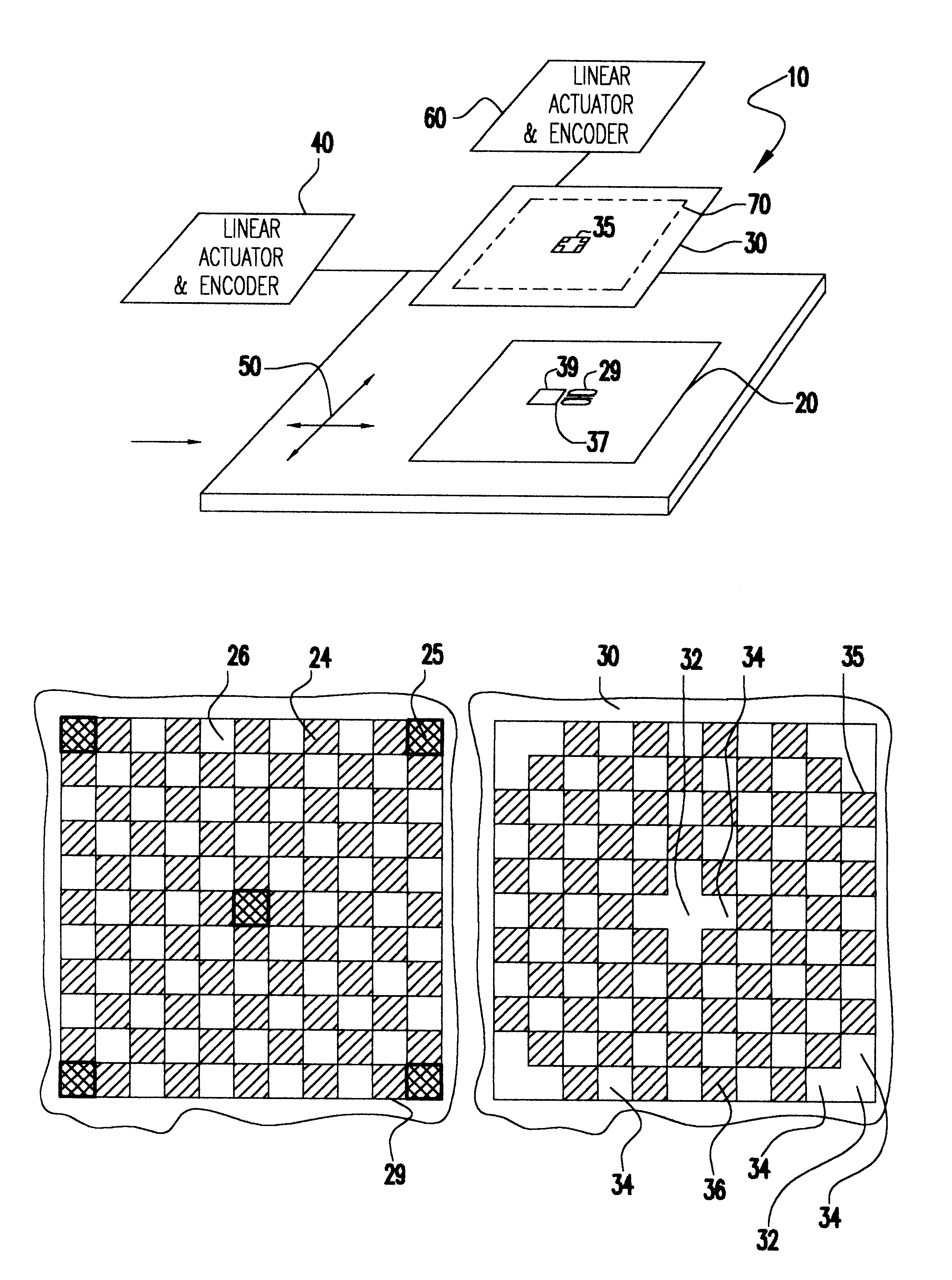
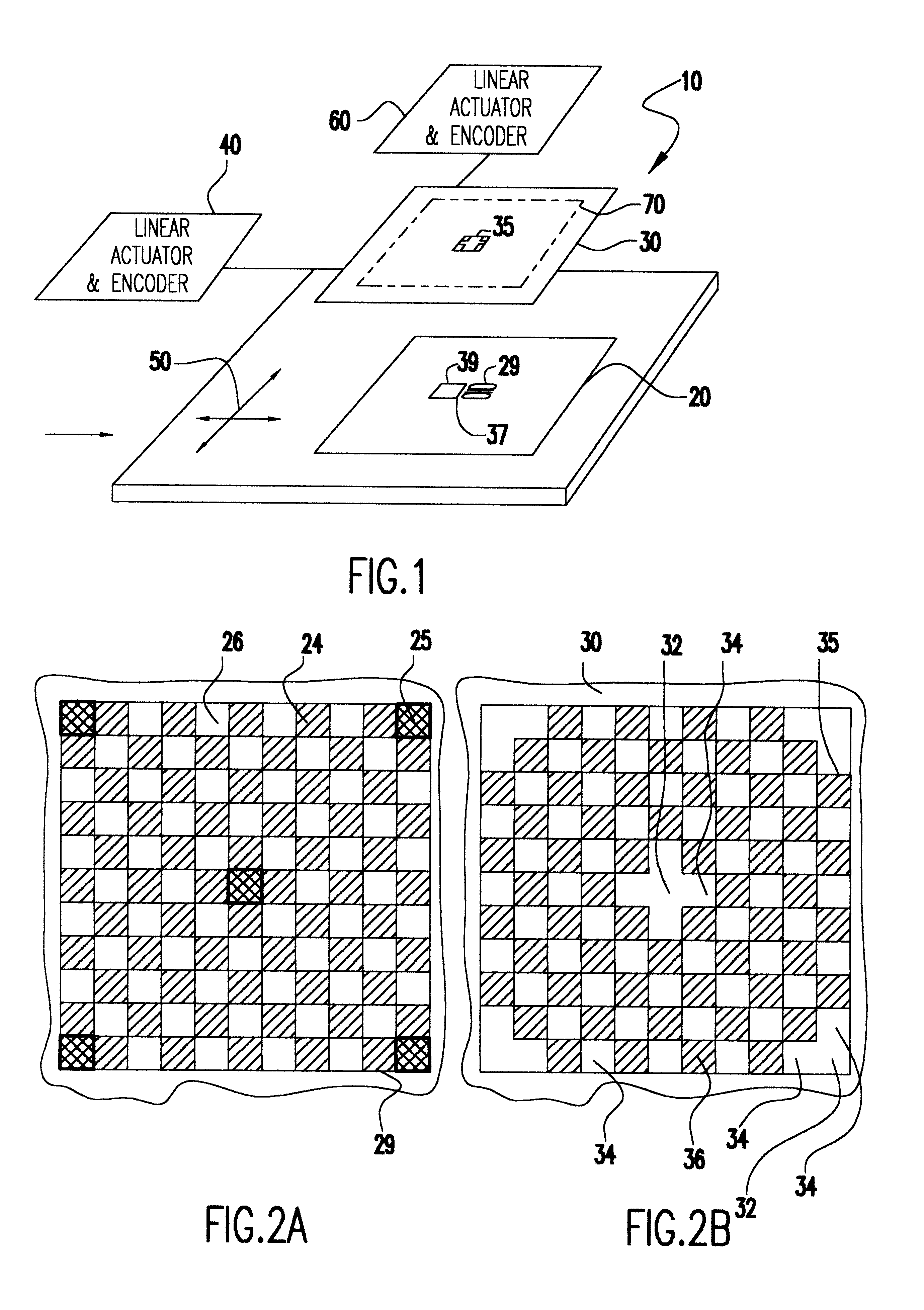
Referring now to the drawings, and more particularly to FIG. 1, there is shown an exploded view of an adjustable transmissivity compound reticle arrangement 10 in accordance with the invention. The compound reticle comprises at least two reticle layers 20, 30, which are preferably placed in close proximity with one layer overlaying the other. One of the reticle layers, preferably reticle layer 30, is movable relative to the other reticle layer by a linear actuator 40, such as a small piezoelectric motor. A position encoder can also be provided in combination therewith to improve positional accuracy and / or provide monitoring of the position of reticle layer 30. An additional linear actuator and position encoder 60 may also be provided for translation in orthogonal directions. Reticle layer 30 in combination with reticle layer 20 thus functions as a shutter as will be described below.

The order in which the layers are stacked is substantially immaterial to the practice of the invention...


PUM


Abstract

A compound reticle having generally complementary clear and opaque areas on a portion of subfield in each of two reticle layers which can be moved relative to each other form a variable transmissivity shutter to regulate charged particle beam intensity independently of source beam current. Either homogeneous or inhomogeneous (e.g. having local variations in beam current density) can be produced at will and in rapid succession to study effects of beam current on beam pattern resolution and aberrations as well as optimum focus for particular patterned subfields having respectively differing transmissivities.

Description

DESCRIPTION1. Field of the InventionThe present invention generally relates to charged particle beam systems and, more particularly, to control of beam current in electron beam projection lithography tools.2. Description of the Prior ArtLithographic processes are utilized in the manufacture of many diverse types of devices, particularly when very small areas must be selectively defined and / or operated upon, as in semiconductor integrated circuit manufacture. At least one lithographic process is invariably required for initial definition of locations and basic dimensions of devices such as transistors and capacitors in integrated circuits.Lithographic processes currently used for integrated circuit manufacture involve the selective exposure of areas of a resist coated on a surface. In general, depending on whether the resist is of a positive or negative type, subsequent development will selectively remove either the exposed or unexposed areas leaving other areas substantially unaffec...

Claims


Application Information

Patent Timeline
IPC IPC(8): H01J37/304H01J37/30
CPCH01J37/304H01J2237/3175H01J2237/30444
Inventor GORDON, MICHAEL S.
Owner NIKON CORP
Why Eureka
Try Eureka