
Plzt capacitor on glass substrate

a technology of glass substrate and capacitor, applied in the field of capacitors, can solve the problems of inability to bend or roll capacitors formed on this substrate to meet certain packaging requirements, ni foil requires polishing and oxidizing quickly,

Active Publication Date: 2015-04-30
DELPHI TECH IP LTD +1
View PDF2 Cites 2 Cited by
  • Summary
  • Abstract
  • Description
  • Claims
  • Application Information

AI Technical Summary

Benefits of technology

The patent describes a capacitor structure that includes a substrate made of glass, a first metallization layer, a layer of lead-lananthanum-zirconium-titanate (PLZT) as a dielectric, and a second metallization layer. The method of forming the capacitor involves depositing the first metallization layer on the substrate, then depositing a layer of PLZT over the first metallization layer, and finally depositing the second metallization layer on top of the PLZT layer. The technical effect of this structure is that it provides a capacitor with improved performance and stability compared to existing structures.

Problems solved by technology

However, Ni foil requires polishing and oxidizes quickly, so an oxygen free working environment is required.
All of these issues make Ni foil a complicated and undesirably expensive substrate material choice.
A Pt coated silicon wafer is rigid, so a capacitor formed on this substrate cannot be bent or rolled to meet certain packaging requirements.
Furthermore, like Ni foil, a Pt coated silicon wafer is also undesirably expensive.

Method used


Image

  • Plzt capacitor on glass substrate
  • Plzt capacitor on glass substrate
  • Plzt capacitor on glass substrate

Examples


Embodiment Construction

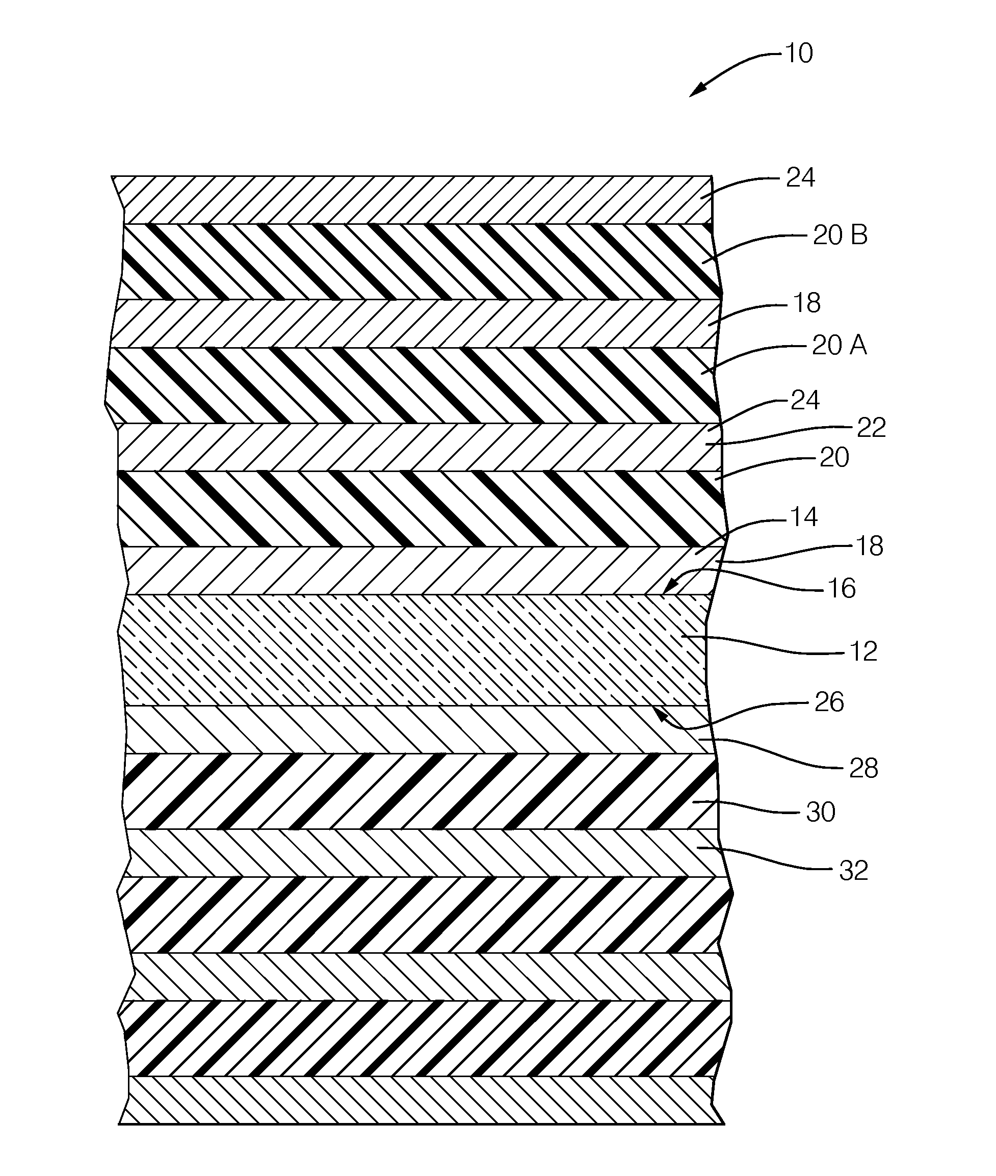
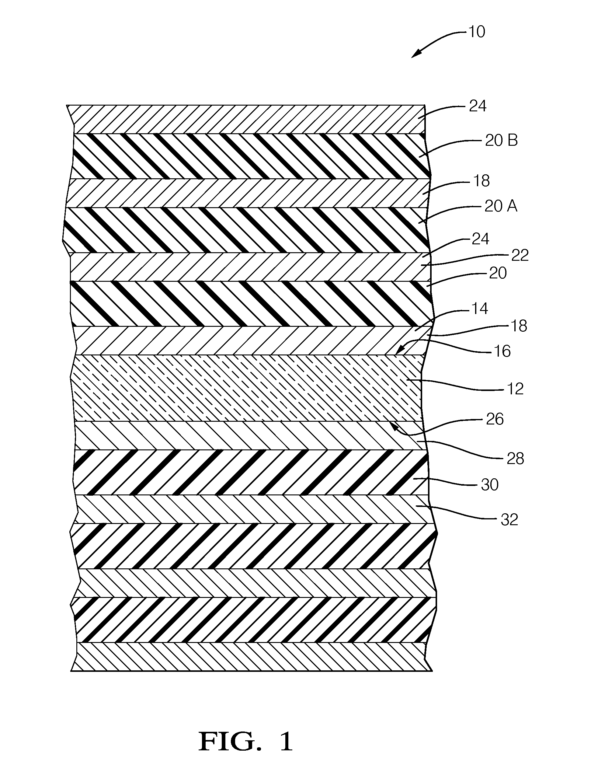
[0010]FIG. 1 illustrates a non-limiting example of the various layers described herein to form a capacitor 10. The relative thickness of the layers illustrated is not meant to infer anything regarding the relative thickness of the actual layers of materials used to form the capacitor 10, but are only shows as different thicknesses to make it easier to visualize the description presented below.

[0011]The capacitor is generally formed or built upon a substrate 12 formed of glass. As used herein, glass is an amorphous (non-crystalline) solid material that exhibits a glass transition, which is the reversible transition in amorphous materials (or in amorphous regions within semi-crystalline materials) from what is often considered a hard and relatively brittle state into a molten or rubber-like state. However, as will be described in more detail below, recent developments in manufacturing thin layers of glass have shown that thin layers can be somewhat flexible. In general, the glass used...


PUM

PropertyMeasurementUnit
thicknessaaaaaaaaaa
radiusaaaaaaaaaa
temperatureaaaaaaaaaa

Abstract

A lead-lanthanum-zirconium-titanate (PLZT) capacitor on a substrate formed of glass. The first metallization layer is deposited on a top side of the substrate to form a first electrode. The dielectric layer of PLZT is deposited over the first metallization layer. The second metallization layer deposited over the dielectric layer to form a second electrode. The glass substrate is advantageous as glass is compatible with an annealing process used to form the capacitor.

Description

GOVERNMENT LICENSE RIGHTS STATEMENT[0001]This is an invention jointly developed by Argonne National Lab and Delphi Automotive System, LLC. The United States Government has rights in this invention pursuant to Contract No. DE-AC02-06CH11357 between the United States Government and UChicago Argonne, LLC representing Argonne National Laboratory and pursuant to Contract No. DE-FC26-07NT43121 between the United States Government / Department of Energy and Delphi Automotive Systems, LLC.TECHNICAL FIELD OF INVENTION[0002]This disclosure generally relates to capacitors, and more particularly relates to a capacitor that uses lead-lanthanum-zirconium-titanate (PLZT) as a dielectric layer and glass as a substrate to form the capacitor.BACKGROUND OF INVENTION[0003]Lead-lanthanum-zirconium-titanate (PLZT) is a ceramic material that has been found to be useful as a capacitor dielectric as PLZT has a high dielectric constant and is capable of relatively high temperature operation, operation up to 15...

Claims


Application Information

Patent Timeline
Patent Type & Authority Applications(United States)
IPC IPC(8): H01G4/12H01G4/30
CPCH01G4/1245H01G4/306H01G4/30H01G4/33H01G4/38H01G4/008H01L28/55H01G4/012H01G4/385
Inventor FAIRCHILD, M. RAYTAYLOR, RALPH S.BERLIN, CARL W.WONG, CELINE WKMA, BEIHAIBALACHANDRAN, UTHAMALINGAM
Owner DELPHI TECH IP LTD
Learn More