Implant design using heterogeneous bone properties and probabilistic tools to determine optimal geometries for fixation features

a technology of heterogeneous bone properties and probabilistic tools, applied in the direction of instruments, prostheses, osteosynthesis devices, etc., can solve the problems of reducing implant stability, achieve the effects of reducing the risk of failure, and reducing the risk of fractur

Inactive Publication Date: 2015-04-30
STRYKER CORP
View PDF5 Cites 48 Cited by
  • Summary
  • Abstract
  • Description
  • Claims
  • Application Information

AI Technical Summary

Benefits of technology

[0006]A first aspect of the present invention is to take advantage of information derived about bone quality in order to achieve an optimized fit between an articular implant and a bone. One characteristic of an optimized fit may include that the engagement between the implant and the bone is less susceptible to failure under various loading scenarios. Another characteristic of an optimized fit may include that the micromotion, stress transmission, and strain of the implant is substantially minimized.
[0007]According to one aspect of the disclosure, a method of designing an implant includes obtaining image data corresponding to at least one bone and deriving bone property information from the image data. A feature of the implant may be determined based at least in part on the derived bone property information. The implant may be manufactured to substantially match the determined feature. The image data may be, for example, CT image data. The image data may also correspond to other suitable imaging methods, including magnetic resonance imaging (“MRI”), Electrical Impedance Tomography, Dual-Energy X-ray Absorptiometry, X-ray, ultrasound, and nuclear imaging, for example. The bone may be a bone of a knee or other joint, or any other bone. The image data may corresponds to a single individual, a population of individuals, or a subpopulation of individuals. The step of deriving the bone property information from the image data may include the step of determining at least one of Hounsfield values, bone density, or elastic modulus. The step of determining the feature of the implant may include creating a virtual bone model, mapping the derived bone property information to the virtual bone model, and superimposing a virtual implant model on the bone model in a desired position, the virtual implant model including one or more virtual fixation features characterized by one or more input parameters. The virtual implant model may be loaded with a virtual physiological load, and finite element analysis may be performed to determine value ranges for at least one of the input parameters of the one or more virtual fixation features. The one or more virtual fixation features of the virtual implant model may be modified based on the determined value ranges for the one or more input parameters. The one or more virtual fixation features may include a bone contacting surface, a peg, or a keel, for example. The one or more input parameters may include at least one input parameter selected from the group consisting of peg location, peg depth, peg angle, peg curvature, peg size, press-fit, peg shape, bone contacting geometry, and surgical placement degrees of freedom. The step of modifying the virtual fixation features of the virtual implant model based on the determined value ranges may substantially minimize one or more of micromotion, stress transmission, and strain.

Problems solved by technology

Variability in bone properties at the location of fixation features results in variable effect on implant fixation and subsequently can result in decreased implant stability.

Method used


Image

  • Implant design using heterogeneous bone properties and probabilistic tools to determine optimal geometries for fixation features
  • Implant design using heterogeneous bone properties and probabilistic tools to determine optimal geometries for fixation features
  • Implant design using heterogeneous bone properties and probabilistic tools to determine optimal geometries for fixation features

Examples


Embodiment Construction

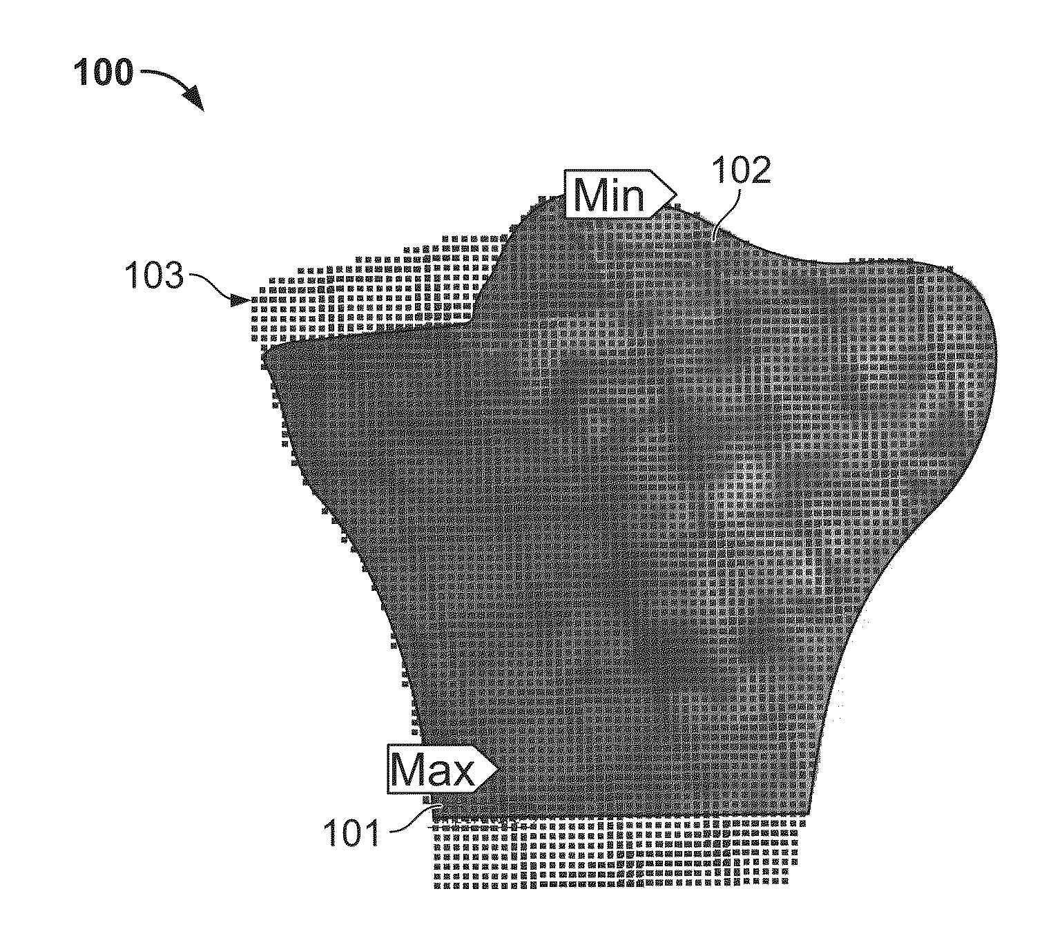
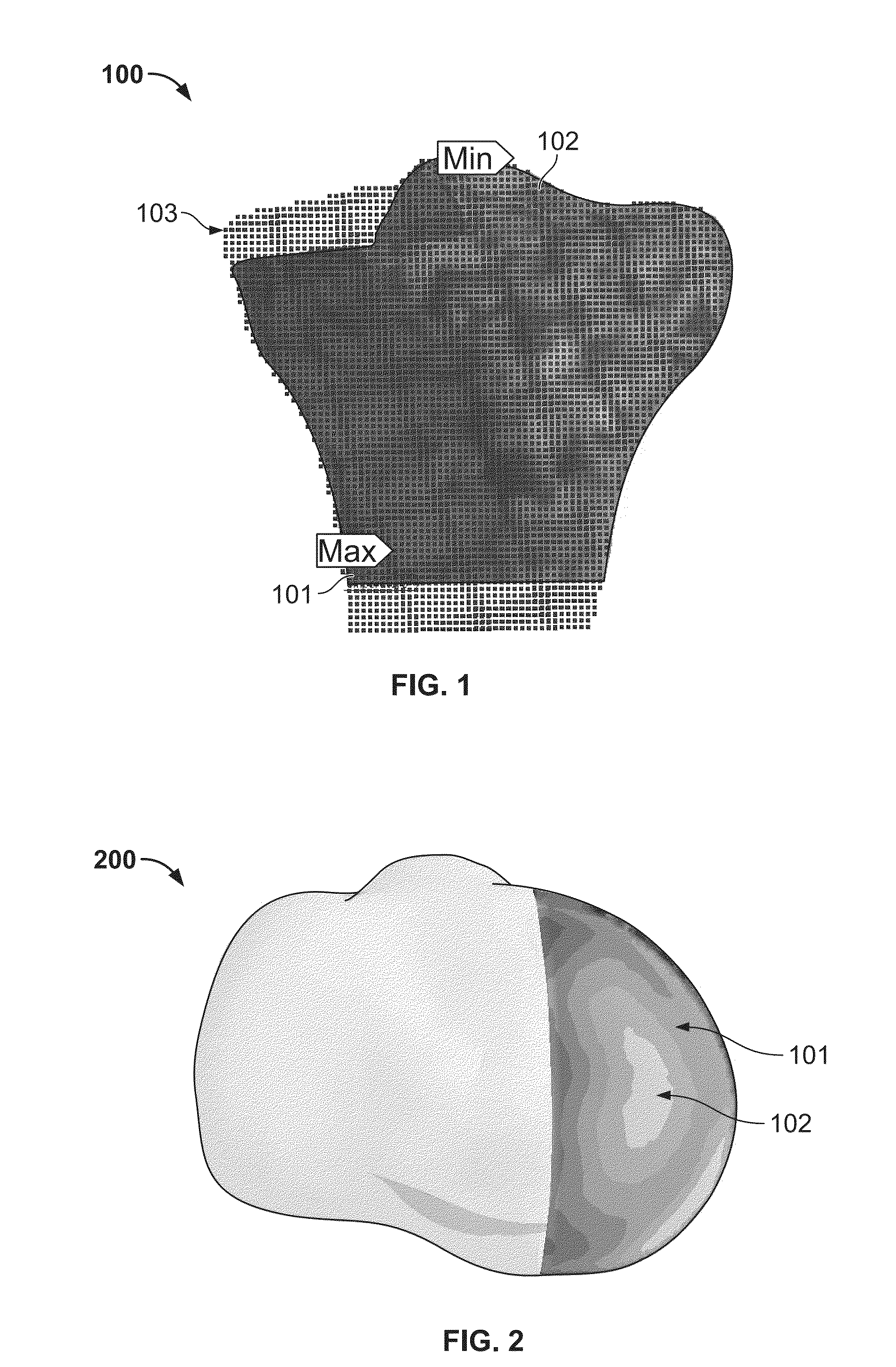
[0019]As described above, bone properties may vary by location within a patient, which, if not accounted for, may be a potential cause of loss of implant stability. Variations in bone properties, or quality of bone, should therefore be incorporated into the design of implant fixation features in order to, for instance, achieve a reduction in excess micromotion, maintain a desirable range of strain and / or stress transmission, minimize the change in strain the bone experiences with an implant compared to healthy native bone in order to prevent stress shielding, and / or minimize the stress and / or strain experienced by cement or other adhesives that facilitate fixation to extend the life of the implant and / or cement. These endpoints may serve as outputs in simulations, as described in greater detail below. More so, by taking into account variations in bone properties, such as bone density, the fit of the articular implant may be less likely to fail during increased loading scenarios.

[002...


PUM


Abstract

An implant, and a method of designing the implant, takes into account heterogeneous bone properties. The method may be directed to designing a fixation feature of the implant using a virtual bone model. Bone property information derived from image data may be mapped to the virtual bone. A virtual model of the implant may be created, including a virtual fixation feature characterized by an input parameter. One or more simulations may be performed, the simulations being of an implantation of the virtual implant on the virtual bone. Values for at least one input parameter may be used for each simulation, each simulation resulting in a value for an output parameter. The input and output values may be analyzed to derive a relationship between the values, the relationship being used to design the fixation feature of the implant.

Description

CROSS-REFERENCE TO RELATED APPLICATIONS[0001]The present application claims the benefit of the filing date of U.S. Provisional Patent Application No. 61 / 896,335 filed Oct. 28, 2013, the disclosure of which is hereby incorporated by reference herein.BACKGROUND OF THE INVENTION[0002]In cementless orthopedic procedures, robust biologic ingrowth is generally a key element to long term implant stability and performance. Biologic ingrowth generally requires sufficient stability of the implant with respect to the adjacent bones and / or tissues particularly during the first 6-8 months after implantation. During this time, bone growth onto a roughened or into a porous surface generally only occurs if the implant is held stably such that the motion of the implant relative to the bone is less than 150 microns.[0003]Implant manufacturers routinely utilize a variety of design features to attempt to provide a press-fit that aids in limiting movement of the implant relative to surrounding anatomica...

Claims


Application Information

Patent Timeline
Patent Type & Authority Applications(United States)
IPC IPC(8): A61F2/30G06F19/00G06F17/50A61F2/28G16Z99/00
CPCA61F2/30942A61F2/28G06F19/3437A61F2002/30006A61F2002/30948A61F2002/30943A61F2002/30014G06F17/5009A61B17/80A61F2002/30955A61F2002/3895A61F2/34A61F2/36A61F2/389A61F2002/30878A61B2034/108G16H50/50G16Z99/00G06F30/20
Inventor DAVIGNON, ROBERTFERKO, MICHAEL C.
Owner STRYKER CORP
Why Eureka
Try Eureka