
Prime mover generator system for simultaneous synchronous generator and condenser duties

Inactive Publication Date: 2015-05-07
BECHTEL POWER CORP
View PDF8 Cites 14 Cited by
  • Summary
  • Abstract
  • Description
  • Claims
  • Application Information

AI Technical Summary

Benefits of technology

The invention is a power train system that includes a prime mover and two or more synchronous machines connected through clutch couplings. The system can operate in three modes: as a generator only, as a condenser only, or simultaneously generating and adjusting reactive power. The system can also include additional synchronous machines and a controller to manage the generators and condensers. The system can be controlled to generate real power and adjust reactive power simultaneously. The technical effects of this invention include the ability to generate and adjust reactive power in the same power train, and the use of a controllable mechanical coupling for synchronous operation of the rotating machines.

Problems solved by technology

Reactive power is a difficult engineering concept to understand.
The difficulty mostly stems from the absence of a robust analogy to simple mechanical systems (e.g., fluid flow in a pipe), which captures all salient features of AC systems, of which reactive power is a vital component, in generation as well as transmission.
If, however, the channel was designed such that only the amount of water that did work was allowed to flow through it, the stream would not be deep enough for the wheel to turn.
The AC system consumes reactive power to keep electricity flowing.
When reactive power is insufficient, voltage drops.
Reactive power shortages are caused by a variety of factors: plant retirements, plant trips, transmission line failures and peak electricity demand.
However, they cannot be switched on / off as fast as SVCs and they cost much more (not to mention the size and weight requiring reinforced concrete foundations).
In particular, line commutated current source converters (CSCs) can only operate with the AC current lagging the voltage, so the conversion process demands reactive power.

Method used


Image

  • Prime mover generator system for simultaneous synchronous generator and condenser duties
  • Prime mover generator system for simultaneous synchronous generator and condenser duties
  • Prime mover generator system for simultaneous synchronous generator and condenser duties

Examples


Embodiment Construction

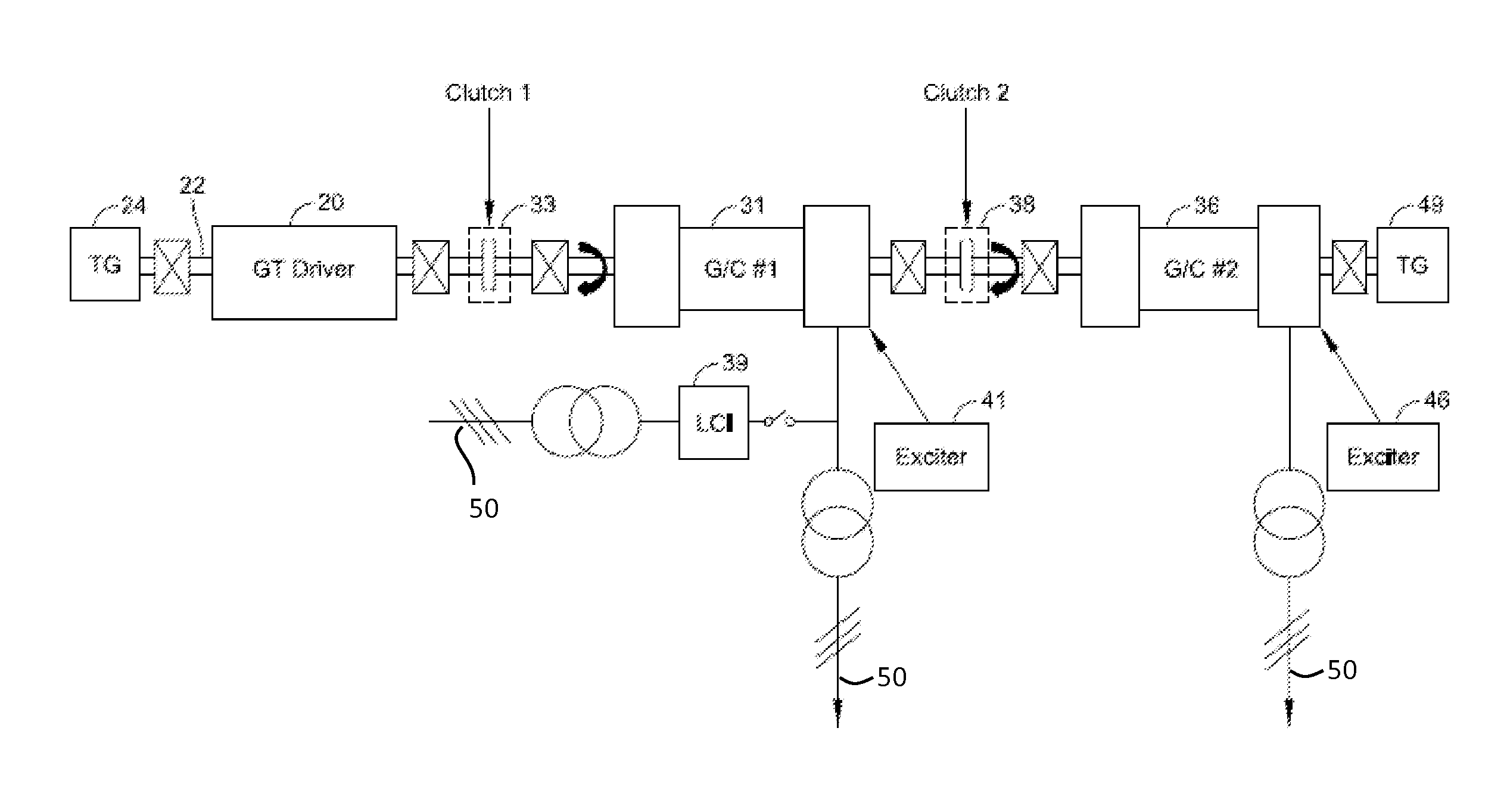
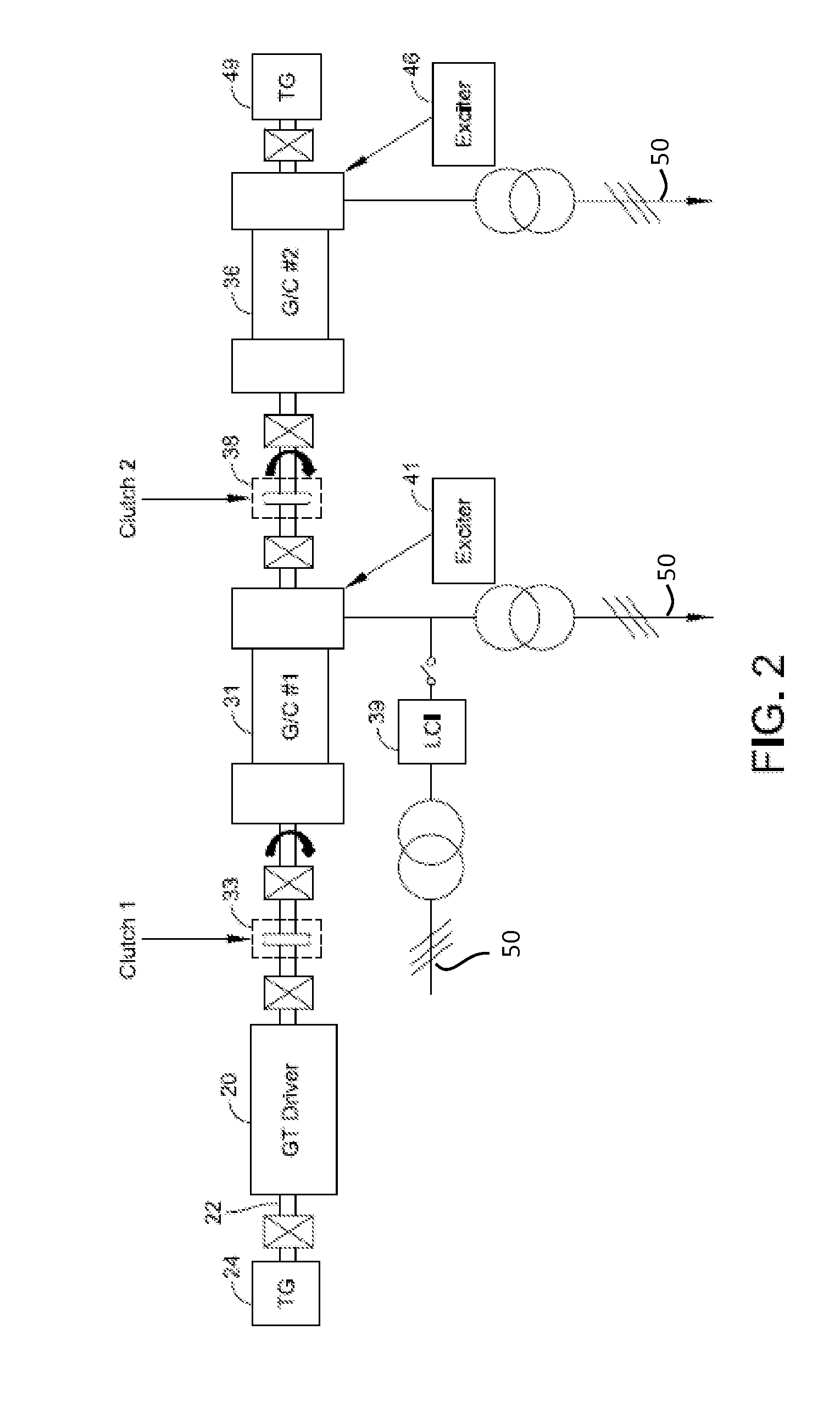
[0041]An electric power generation system according to the invention applies a source of mechanical torque to a coupled set of at least two synchronous rotating machines and operates the synchronous machines selectively as generators, synchronous condensers, or advantageously to serve as one or more generators and one or more synchronous condensers operating simultaneously, coupled to a power transmission line leading to various electrical loads.

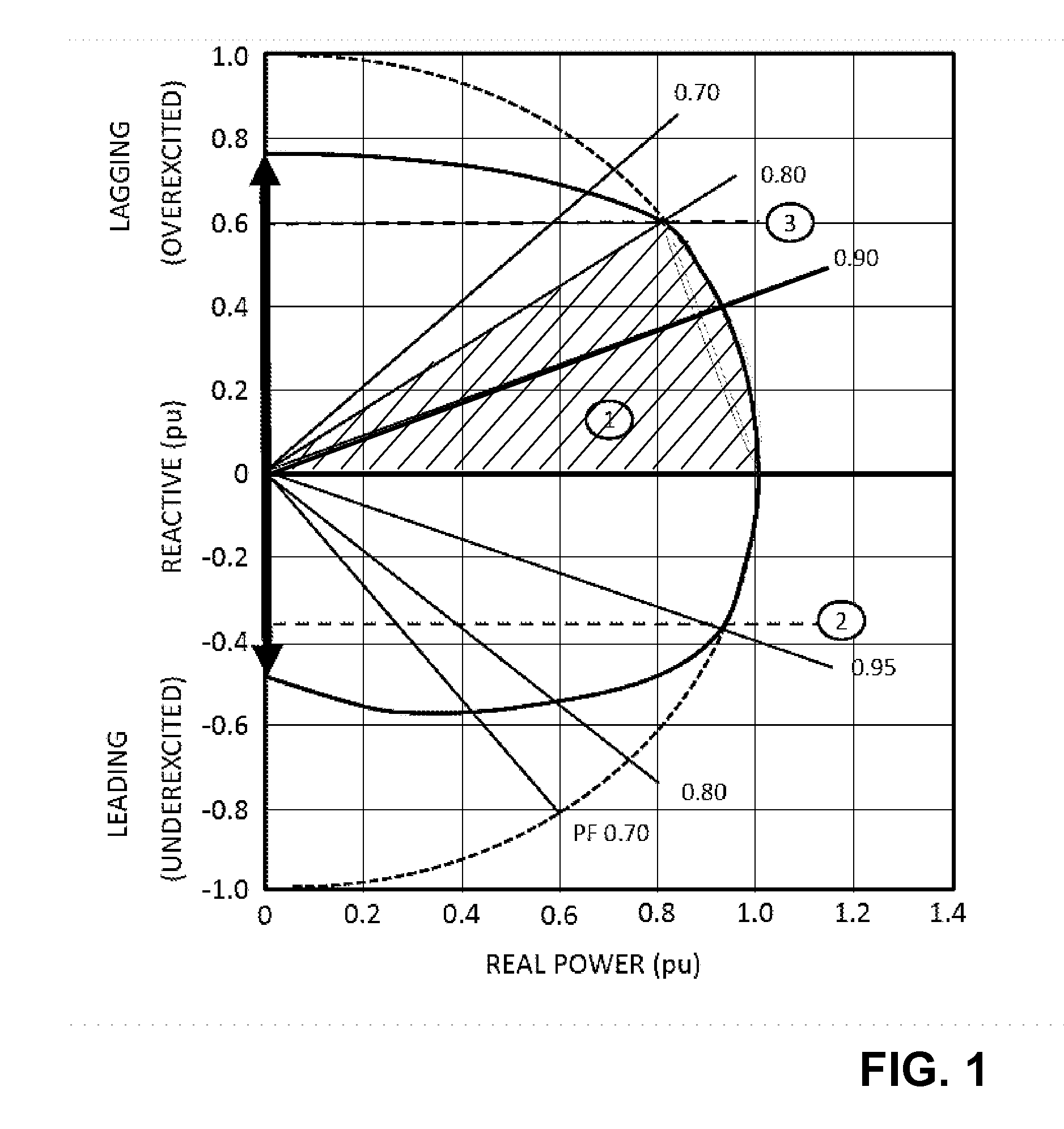
[0042]An alternating current electric power source coupled to a theoretical wholly resistive load is characterized by current and voltage AC characteristics that are in phase. A practical load, however, is partly resistive and partly reactive, i.e., capacitive or inductive. In that case, an AC power signal from a generator is associated with an AC current signal that leads or lags the voltage signal in phase to account for the di / dt characteristics of the reactive loads as the capacitive and inductive elements charge and discharge. FIG. 1 sh...


PUM


Abstract

An electric power generation plant has at least two synchronous machines and a source of mechanical power (torque), coupleable such that one or more of the synchronous machines can be operated as a generator while one or more is operated as a synchronous condenser. Field exciters, controlled shaft couplings, starters and switching sequences control starting, restarting and switching into simultaneous operation as generators, as condensers, or as one or more generators and condensers synchronously coupled to one another along a drive train. The disclosed configurations include modifications of existing generator installations such as decommissioned plants, such as by controllably coupling a second synchronous machine to a drive train, for use as a condenser for power factor control when needed or as an added source of generator capacity during times of high demand.

Description

FIELD OF THE INVENTION[0001]This invention concerns methods and apparatus for coupling two or more synchronous rotating electrical machines to a prime mover driver (such as a steam, gas or water turbine, a diesel engine, etc.) that supplies torque to a drive train using shaft couplings and associated controls selectively to cause either or both of the electrical machines to work as a generator of real power to an electrical power transmission system, or as a synchronous condenser to supply reactive power to the system. In addition to supporting different operational conditions, provisions are made for starting, stopping, switching over and synchronizing rotation of the two or more rotating machines and the prime mover, using controllable shaft coupling elements.BACKGROUND[0002]Synchronous machines belong to a special class of rotating electrical machines, whose shaft rotational speed corresponds to an alternating current (AC) due to periodic alignment and misalignment of magnetic po...

Claims


Application Information

Patent Timeline
IPC IPC(8): H02P9/02
CPCH02P9/02H02P9/14
Inventor GULEN, SEYFETTIN C.BOULDEN, MARK S.
Owner BECHTEL POWER CORP
Learn More