
DC link capacitance measurement for electric vehicle drivetrain

a technology of dc link capacitor and electric vehicle, which is applied in the direction of electric devices, instruments, transportation and packaging, etc., can solve the problems of increased costs, loss of proper functioning of inverters, and deterioration of film capacitors in particular

Active Publication Date: 2015-05-14
FORD GLOBAL TECH LLC
View PDF10 Cites 28 Cited by
  • Summary
  • Abstract
  • Description
  • Claims
  • Application Information

AI Technical Summary

Benefits of technology

The patent describes a method for detecting when a capacitor between a DC power source and an inverter load is wearing out. The method involves measuring the voltage and current during the process of discharging the capacitor and calculating the capacitance to monitor any decline that could indicate a failure. The technical effect of this patent is to provide a way to prevent failures in power conversion systems caused by worn-out components, leading to higher reliability and efficiency.

Problems solved by technology

The DC link capacitor performance is vital to the functioning of the inverter system, and any degradation in its properties can lead to a loss of proper functioning of the inverter.
During extended use, film capacitors in particular may be subject to deterioration as a result of high operating temperatures, high operating voltages (e.g., voltage spikes), high humidity, and manufacturing defects such as impurities or film defects.
This allows a higher confidence in withstanding worst case conditions but results in increased costs.

Method used


Image

  • DC link capacitance measurement for electric vehicle drivetrain
  • DC link capacitance measurement for electric vehicle drivetrain
  • DC link capacitance measurement for electric vehicle drivetrain

Examples


Embodiment Construction

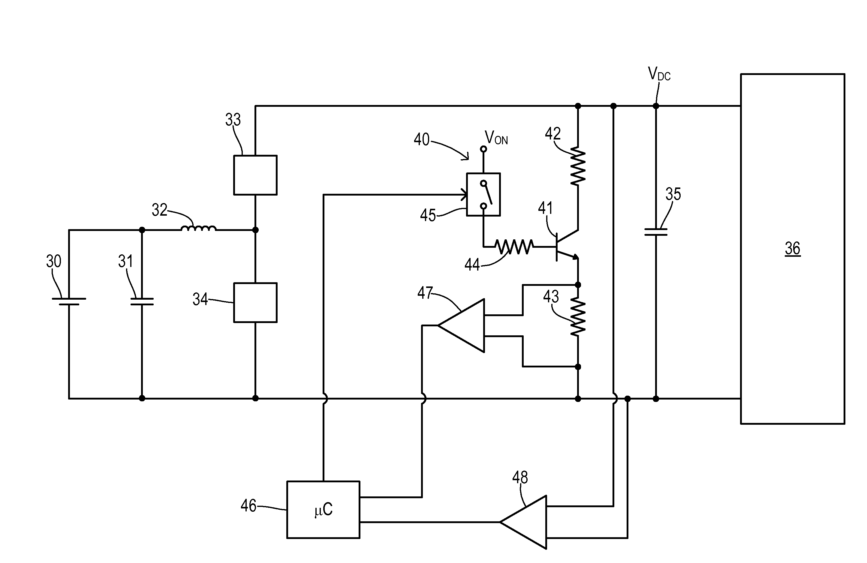
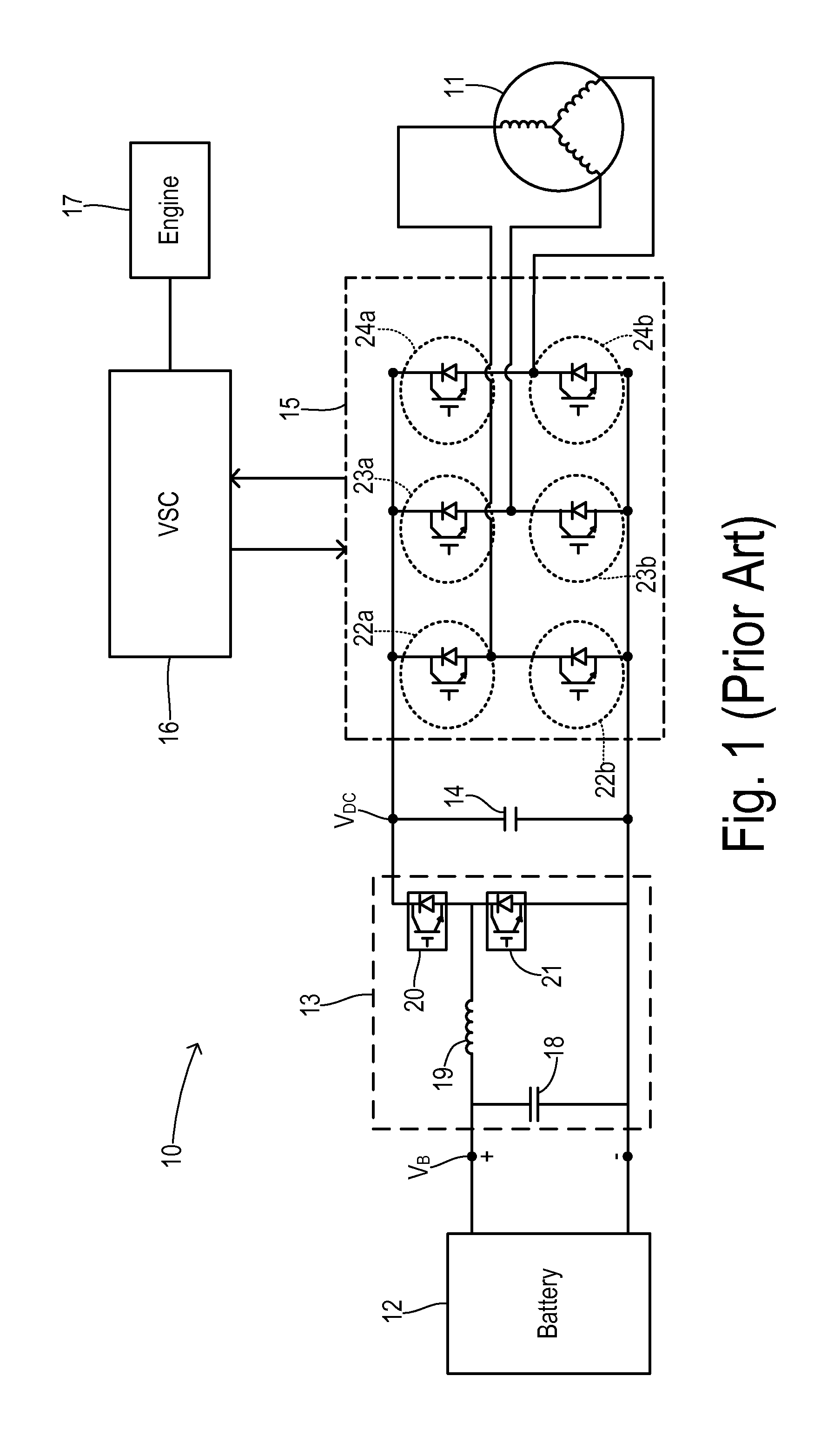
[0015]FIG. 1 shows a vehicle 10 having an electric drivetrain with a traction motor 11 and a battery 12. A battery voltage VB from battery 12 is converted by a boost converter 13 to a higher voltage VDC across a DC link capacitor 14. The converted DC voltage is inverted in a PWM inverter 15 for supplying an alternating voltage to traction motor 11. A vehicle system controller (VSC) 16 is connected to inverter 15 for implementing a known type of control strategy when the electric drivetrain is activated. In the case where vehicle 10 is a hybrid electric vehicle, VSC 16 is also coupled with a combustion engine 17 for operating vehicle 10 in gas-powered modes as known in the art.

[0016]In the illustrated embodiment, boost converter 13 includes a capacitor 18 and an inductor 19 connected to battery 12. A pair of power transistors 20 and 21 are selectably switched on and off at predetermined time intervals as known in the art in order to generate the desired voltage VDC. Each power switch...


PUM


Abstract

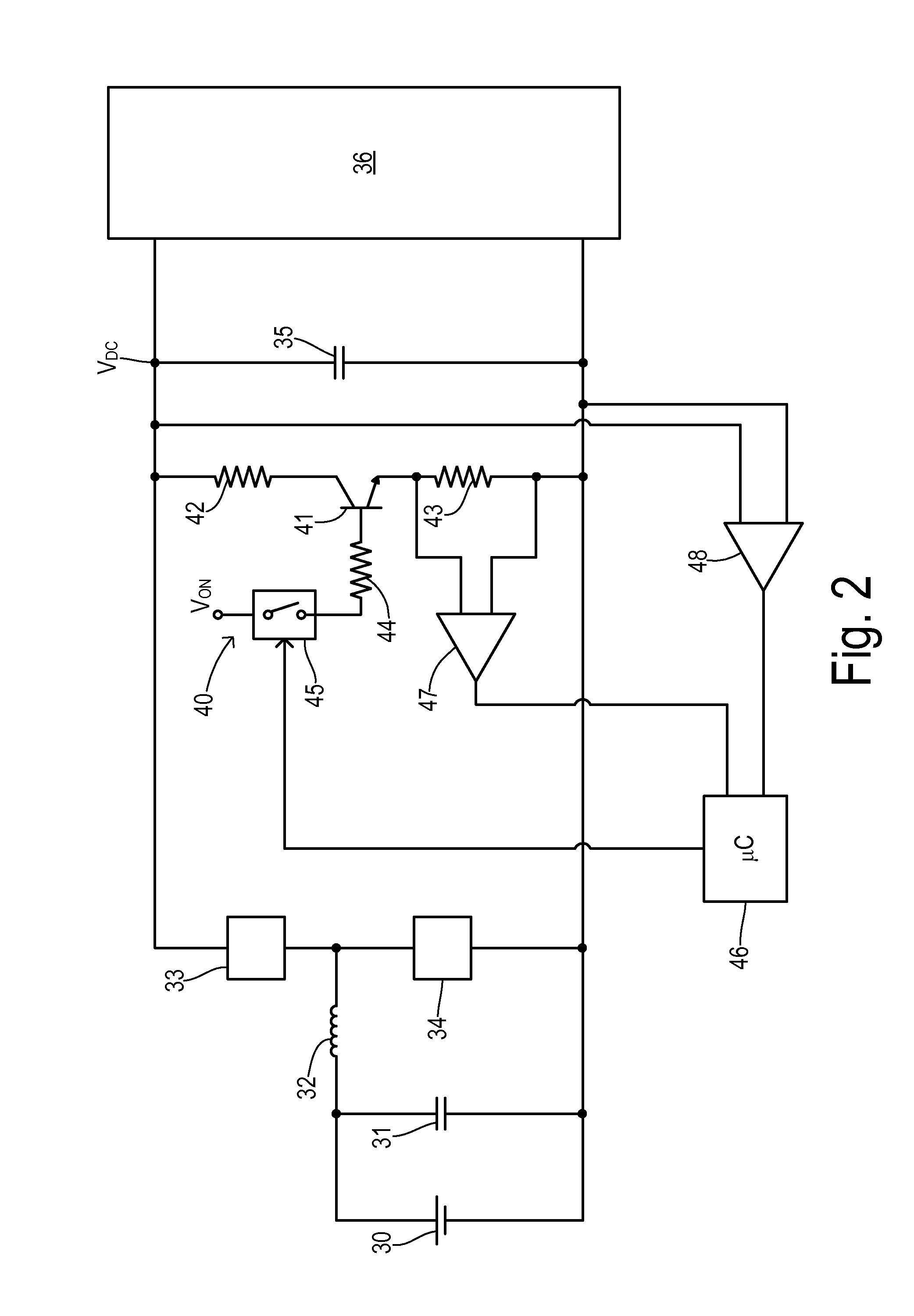
In order to detect deterioration of a DC link capacitor between a DC source and an inverter load in an electric propulsion vehicle, capacitance of the link capacitor must be accurately measured during in-service use. A charge is established on the link capacitor. The capacitor is isolated from the source and the inverter load. A constant current circuit is activated to discharge the capacitor. A first voltage is measured across the capacitor at a first time during the discharging. A second voltage is measured across the capacitor at a second time during the discharging. A discharge current flowing from the capacitor is measured during the discharging. The capacitance is calculated in response to the discharge current multiplied by a ratio of a difference between the second and first times to a difference between the first and second voltages. The calculated capacitance is monitored for a decline indicative of a failure.

Description

CROSS REFERENCE TO RELATED APPLICATIONS[0001]Not Applicable.[0002]STATEMENT REGARDING FEDERALLY SPONSORED RESEARCH[0003]Not Applicable.BACKGROUND OF THE INVENTION[0004]The present invention relates in general to electric drive circuits for road vehicles, and, more specifically, to measuring the capacitance of a DC link capacitor to support determination of a state of health of the link capacitor.[0005]Electric drive systems for traction motors in electric and / or hybrid road vehicles typically require conversion of electrical power from a DC source to an alternating current signal at a variable frequency and power for driving an AC traction motor. The DC source itself may include a storage device such as a battery or fuel cell and a DC-to-DC converter for stepping up the DC voltage supplied to the AC inverter. A necessary component for coupling the DC source (e.g., the battery or an intermediate DC-to-DC converter) to the DC-to-AC inverter is a DC link capacitor.[0006]In automotive v...

Claims


Application Information

Patent Timeline
IPC IPC(8): G01R31/02B60L11/02G01R27/26B60L50/10
CPCG01R31/028B60L11/02G01R27/2605B60L3/003B60L2240/526B60L2240/527B60L2240/529B60L50/10G01R31/64Y02T10/7072Y02T10/70
Inventor GOVINDARAJ, ARVINDLEI, GUANGYINBLACKMAN, MANSUR A.CHEN, CHINGCHI
Owner FORD GLOBAL TECH LLC
Learn More