Piezoelectric composites and methods of making

a composite material and composite technology, applied in the field of piezoelectric composite materials, can solve the problems of ectopic bone formation, substantial risk of complication, and user compliance with externally worn devices

Inactive Publication Date: 2015-05-14
UNIVERSITY OF KANSAS
View PDF4 Cites 46 Cited by
  • Summary
  • Abstract
  • Description
  • Claims
  • Application Information

AI Technical Summary

Benefits of technology

[0031]Suitably, the chains that are formed in the composite have a random orientation. In other embodiments, at least about 10% of the chains are aligned to within about ±10 degrees

Problems solved by technology

However, in its current form, it is hampered by limitations such as the need for a battery pack or a separate implantable device to provide power, and reliance on user compliance for externally worn devices.
However, studies on BMP have shown that it has a substantial risk for complication, including ectopic bone formation.
Similar to high performance dielectric materials, piezoceramics are the most often used piezoelectric material, though they tend to be stiff and brittle.
In spinal fusions, the use of such materials has generally been hampered by limitations on the size and shape of curre

Method used


Image

  • Piezoelectric  composites and methods of making
  • Piezoelectric  composites and methods of making
  • Piezoelectric  composites and methods of making

Examples


example 1

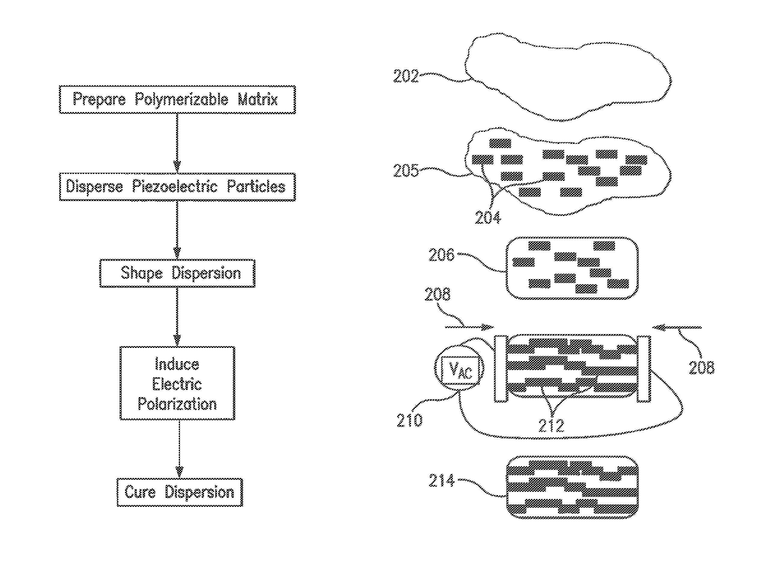
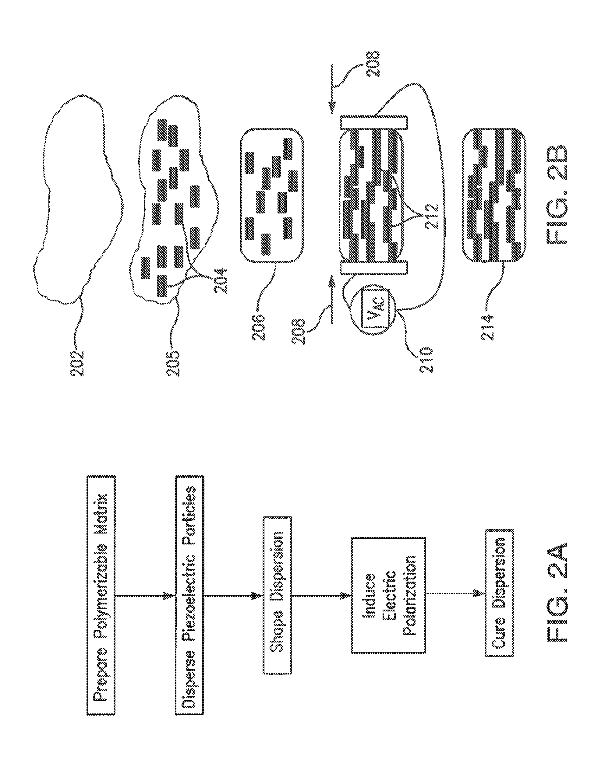
Preparation of 1-3 Composite using DEP

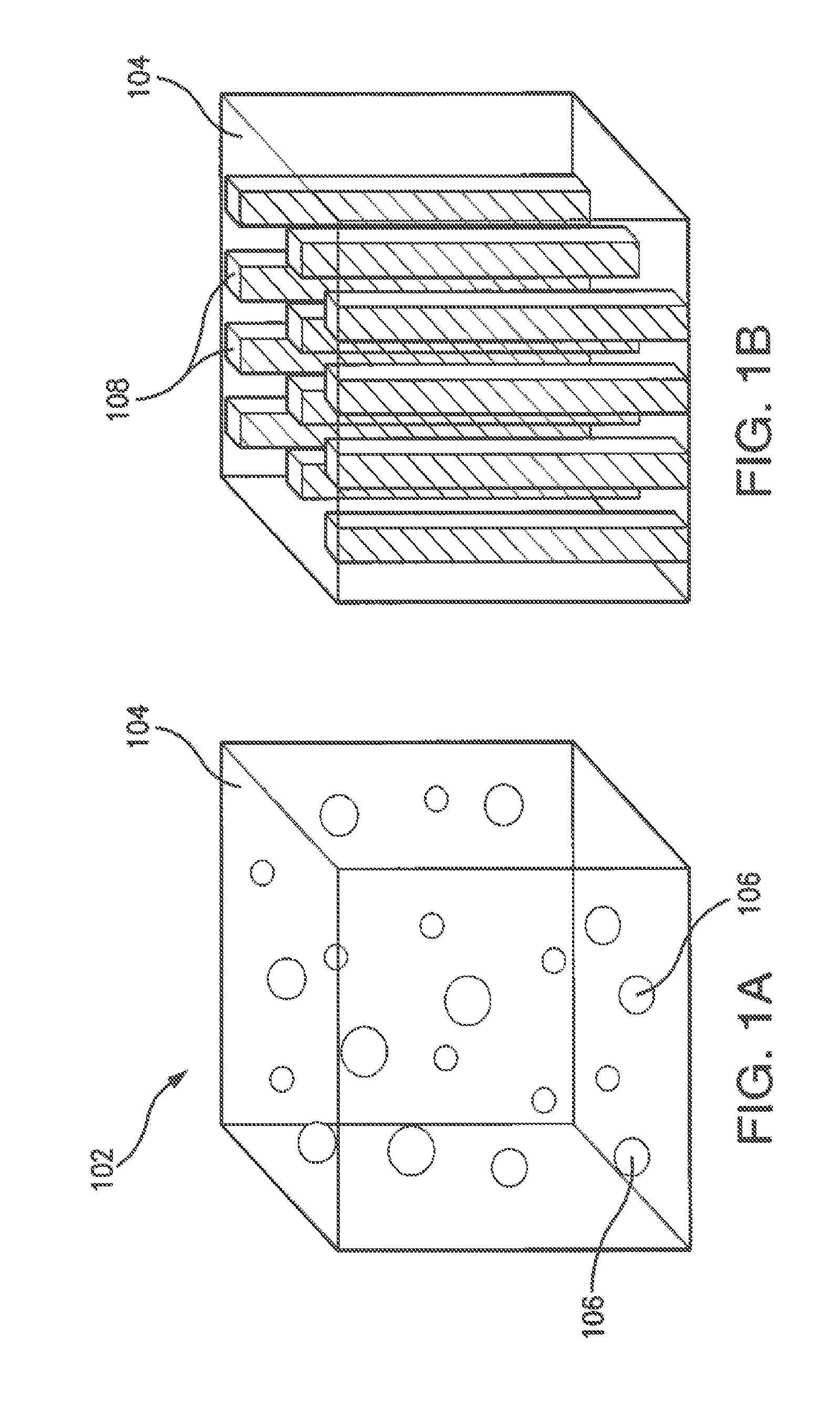
[0186]Structured 1-3 composites were prepared using dielectrophoresis (DEP). The polymerizable matrix for these composites was a two part resin (302-3M, Epotek), and the particles were 5 micrometer barium titanate. Composites were structured using an electric field strength of 1 KV / mm and a frequency of 1 KHz. The resulting dielectric and piezoelectric properties of the composite materials were characterized using well-known techniques as described below.

[0187]Dielectric characterization was conducted using a Hioki 3522-50 LCR meter (Hioki EE Corporation, Negano, Japan). This meter is used to assess the capacitance, and resistance of the samples. This information, coupled with knowledge of sample geometry, can be used to determine a sample's resistivity, conductivity, and dielectric constant. The meter can also assess the dielectric loss factor (tan ∂). Measurements are carried out at room temperature, at frequencies from DC to 1 KHz. Confidence...

example 2

Piezoelectric Composite Spinal Fusion Interbody Implant

[0204]Provided herein is the development of a piezoelectric composite biomaterial and interbody device (spinal implant) design for the generation of clinically relevant levels of electrical stimulation to help improve the rate of fusion for in patients.

[0205]A lumped parameter model of the piezoelectric composite implant was developed based on a model that has been utilized to successfully predict power generation for piezoceramics. Seven variables (fiber material, matrix material, fiber volume fraction, fiber aspect ratio, implant cross-sectional area, implant thickness, and electrical load resistance) were parametrically analyzed to determine their effects on power generation within implant constraints. Influences of implant geometry and fiber aspect ratio were independent of material parameters. For a cyclic force of constant magnitude, implant thickness was directly and cross-sectional area inversely proportional to power ge...


PUM

PropertyMeasurementUnit
Lengthaaaaaaaaaa
Fractionaaaaaaaaaa
Fractionaaaaaaaaaa

Abstract

There is a need for methods that can produce piezoelectric composites having suitable physical characteristics and also optimized electrical stimulatory properties. The present application provides piezoelectric composites, including tissue-stimulating composites, as well as methods of making such composites, that meet these needs. In embodiments, methods of making a spinal implant are provided. The methods suitably comprise preparing a thermoset, thermoplastic or thermoset/thermoplastic, or copolymer polymerizable matrix, dispersing a plurality of piezoelectric particles in the polymerizable matrix to generate dispersion, shaping the dispersion, inducing an electric polarization in the piezoelectric particles in the shaped dispersion, wherein at least 40% of the piezoelectric particles form chains.

Description

BACKGROUND OF THE INVENTION[0001]1. Field of the Invention[0002]The present application relates to piezoelectric composites comprising polymerizable matrices and piezoelectric particles dispersed therein. Suitably the composites are useful as tissue-stimulating materials, including spinal implants. The present application also relates to methods of making piezoelectric composites.[0003]2. Background of the Invention[0004]Electrical stimulation has proven to be an effective therapy to increase the success rate of spinal fusions, especially in the difficult-to-fuse population. However, in its current form, it is hampered by limitations such as the need for a battery pack or a separate implantable device to provide power, and reliance on user compliance for externally worn devices. An alternative treatment to aid in bone growth stimulation involves the use of growth factors such as bone morphogenic protein (BMP). However, studies on BMP have shown that it has a substantial risk for com...

Claims


Application Information

Patent Timeline
IPC IPC(8): A61F2/30A61L27/44B29C71/00B29C47/00B29C43/00B29C49/00B29C51/00A61F2/44B29C45/00
CPCA61F2/30771A61F2/4455A61L27/446B29C71/0072B29C45/0001B29C43/003B29K2301/00B29C51/002B29C47/0004A61F2002/30087A61F2002/3093B29C2049/001B29L2031/7532B29C49/0005A61L27/50A61L2430/38A61F2002/2821B29C48/022H10N30/852H10N30/045H10N30/092
Inventor FRIIS, ELIZABETH ANNAMARIADOMANN, JOHN PATRICK
Owner UNIVERSITY OF KANSAS
Why Eureka
Try Eureka