Thermoelectric Conversion Module and Method for Making it

a conversion module and thermoelectric technology, applied in the field of thermoelectric modules, can solve the problems of not adapting the configuration, the shunt is not adaptable, and the challenge of using rejected gases with a lower temperatur

Inactive Publication Date: 2015-05-21
UNIVERSITE CATHOLIQUE DE LOUVAIN
View PDF4 Cites 7 Cited by
  • Summary
  • Abstract
  • Description
  • Claims
  • Application Information

AI Technical Summary

Benefits of technology

[0028]Preferably, said first, second and third thermal resistor elements comprise a same thermally insulating material of thermal conductivity κr, and said first, second and third thermal bridge element elements comprise a same thermally conductive material of thermal conductivity κc, and such that

Problems solved by technology

However, there is a big challenge in using rejected gases that have a lower temperature.
Moreover, such a configuration is not adapted when one aims at having a thermoelectric module having the form of a layer or a plate with a small thickness because of the two following reasons.
Such shunts are not adapted if one aims at having a thermoelectric module that has

Method used


Image

  • Thermoelectric Conversion Module and Method for Making it
  • Thermoelectric Conversion Module and Method for Making it
  • Thermoelectric Conversion Module and Method for Making it

Examples


Embodiment Construction

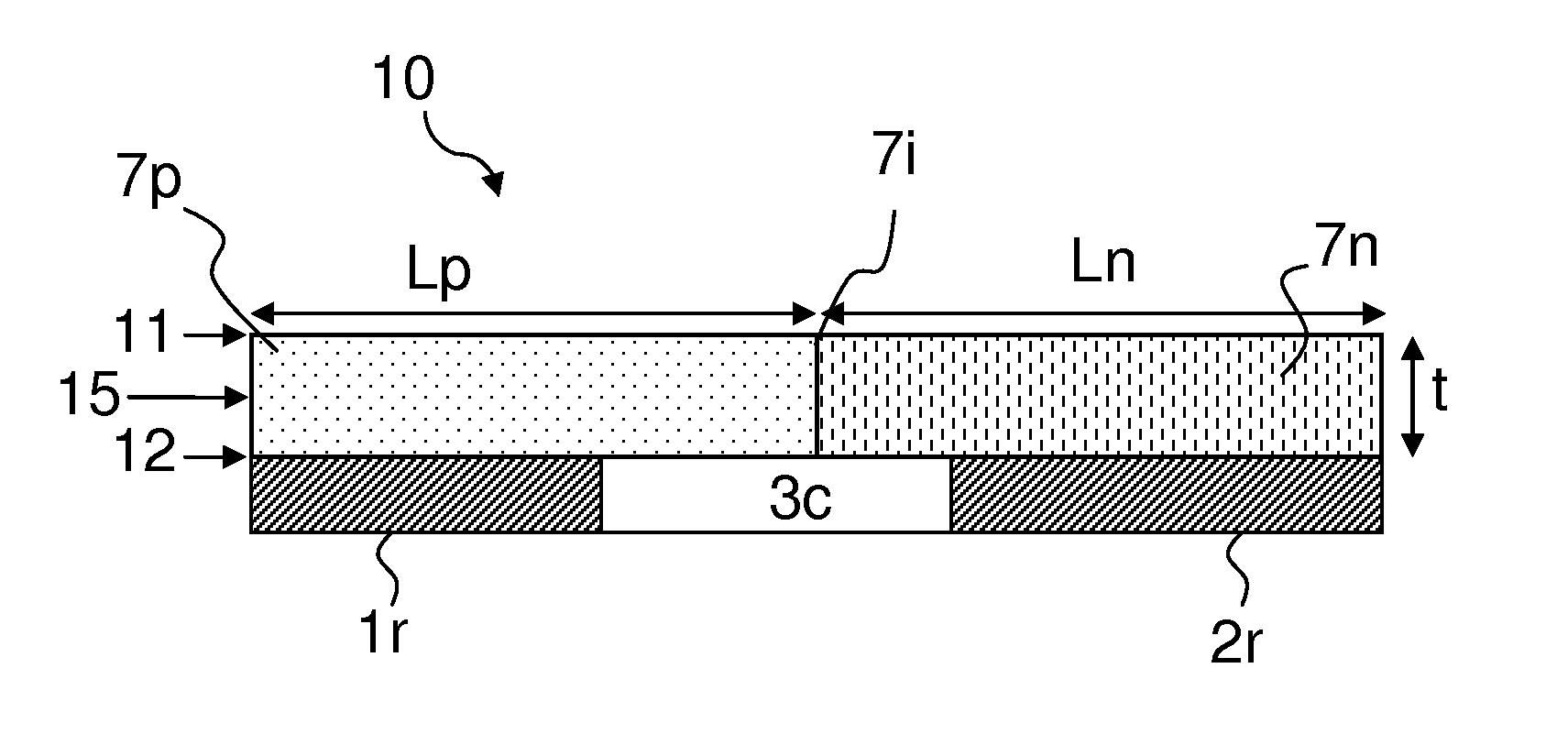
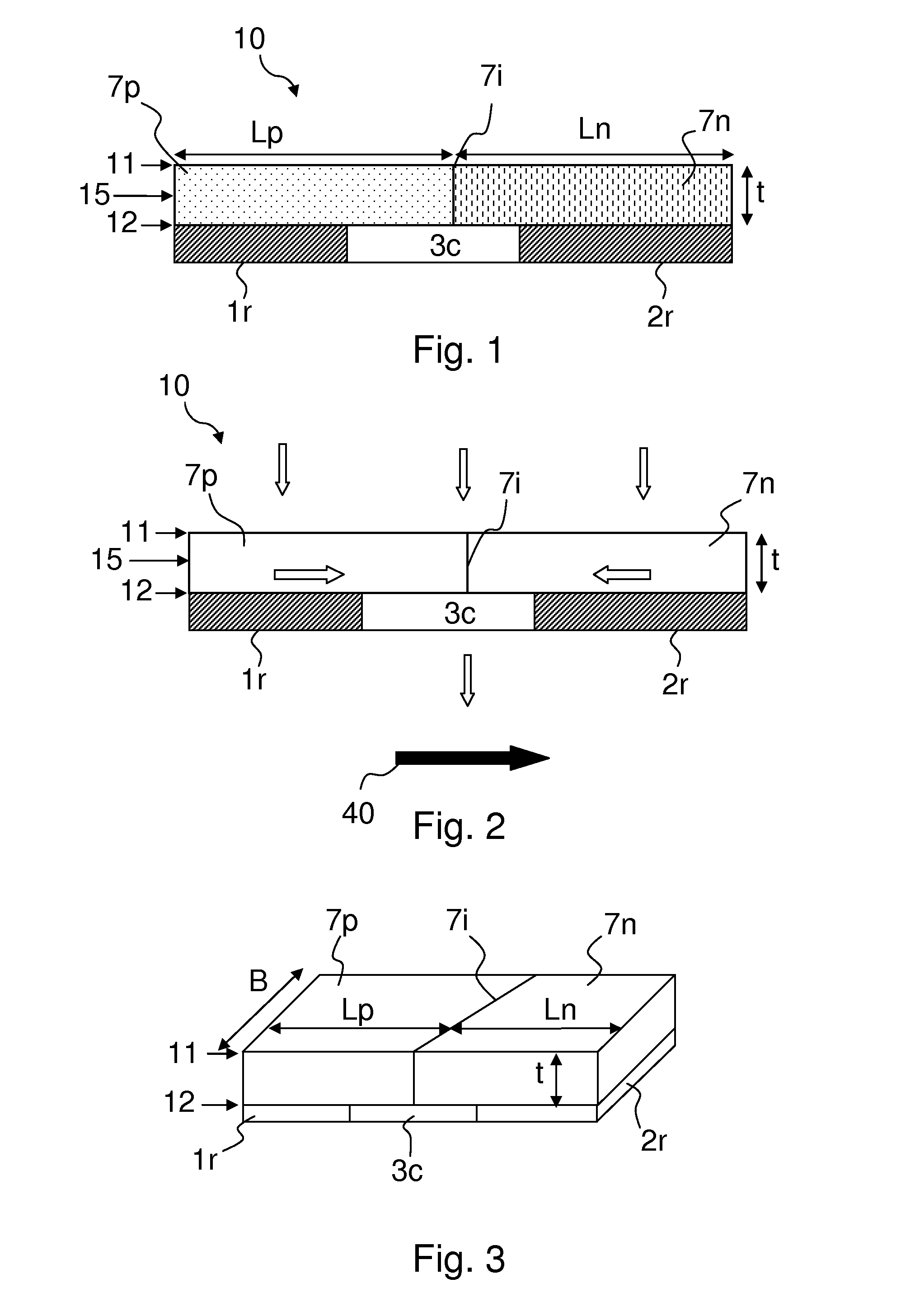
[0058]FIG. 1 shows a first embodiment of the thermoelectric module 10 according to the invention. The thermoelectric module 10 comprises a thermoelectric layer 15 of substantially constant thickness t. The thermoelectric layer 15 comprises an upper 11 and a lower 12 main surfaces that are separated by the thickness t. The thermoelectric layer 15 also comprises one p-type 7p and one n-type 7n portions. Each portion (7p, 7n) extends over the whole thickness t of the thermoelectric layer 15. Preferably, the whole thermoelectric layer 15 is made of a same material that presents a spatial variation of its doping in order to obtain the p-type 7p and n-type 7n portions. The terms ‘p-type’ and ‘n-type’ are known by the one skilled in the art. In another preferred embodiment, the p-type 7p and n-type 7n portions are made of two different materials. The thickness t is preferably comprised between 1 mm and 10 mm, and is more preferably equal to 8 mm. However, a larger or a smaller thickness t ...


PUM


Abstract

According to a first aspect, the invention relates to a thermoelectric module (10) that comprises a thermoelectric layer (15) comprising one p-type (7p) and one n-type (7n) portions presenting together an upper and a lower main surfaces (11,12). The thermoelectric module (10) further comprises a first and a second thermal resistor elements (1r, 2r), and a first thermal bridge element (3c), between and adjacent to the first and second thermal resistor elements (1r, 2r). The first and second thermal resistor elements (1r, 2r) and the first thermal bridge element (3c) cover the whole lower main surface (12). The p-type (7p) and the n-type (7n) portions are adjacent and directly coupled by an interface (7i). The first thermal bridge element (3c) spans at least over the orthogonal projection of the interface (7i) on the lower main surface (12).

Description

FIELD OF THE INVENTION[0001]According to a first aspect, the invention relates to a thermoelectric module. According to a second aspect, the invention relates to an assembly of at least two thermoelectric modules. According to a third aspect, the invention relates to a process for making a thermoelectric module.DESCRIPTION OF PRIOR ART[0002]A major part of energy waste in industrial and domestic applications takes the form of thermal energy. High temperature (>400° C.) rejected gases can be efficiently used. However, there is a big challenge in using rejected gases that have a lower temperature. Thermoelectric converters or thermal conversion modules using the Seebeck effect could be used in order to generate electric energy from such a source of thermal energy. Thermoelectric converters can be used in other applications; for instance they can be used to convert into electricity geothermal energy, heat from sun or heat from the seas. Using the Peltier effect, thermoelectric conve...

Claims


Application Information

Patent Timeline
IPC IPC(8): H01L35/32H01L35/34
CPCH01L35/34H01L35/32H01L2924/0002H10N10/01H10N10/17H01L2924/00
Inventor JACQUES, PASCALSIMAR, AUDEVAN DER REST, CAMILEMATAGNE, ERNESTROY, GEOFFREYSHMITZ, ALAIN
Owner UNIVERSITE CATHOLIQUE DE LOUVAIN
Why Eureka
Try Eureka