Exhaust gas sensor

a technology of exhaust gas sensor and sensor, which is applied in the field of exhaust gas sensor, can solve the problems of requiring high-octane fuel, affecting the performance of the engine, and requiring high-octane fuel, so as to improve the fuel economy of the automobile, improve the compression ratio of the engine, and improve the thermal efficiency

Active Publication Date: 2015-05-28
TOYOTA JIDOSHA KK
View PDF1 Cites 2 Cited by
  • Summary
  • Abstract
  • Description
  • Claims
  • Application Information

AI Technical Summary

Benefits of technology

[0007]Improving thermal efficiency by increasing the compression ratio of the engine is an effective way of improving fuel economy in an automobile. However, knocking occurs readily in engines of high compression ratio, and hence the engine requires a high-octane fuel. Studies in recent years have addressed the addition of Mn-containing additives to fuel in order to increase the octane number of fuel.

Problems solved by technology

However, knocking occurs readily in engines of high compression ratio, and hence the engine requires a high-octane fuel.
Thus, the response in a case where exhaust gas of high oxygen concentration flows into the gas sensor becomes delayed.

Method used


Image

  • Exhaust gas sensor
  • Exhaust gas sensor
  • Exhaust gas sensor

Examples


first embodiment

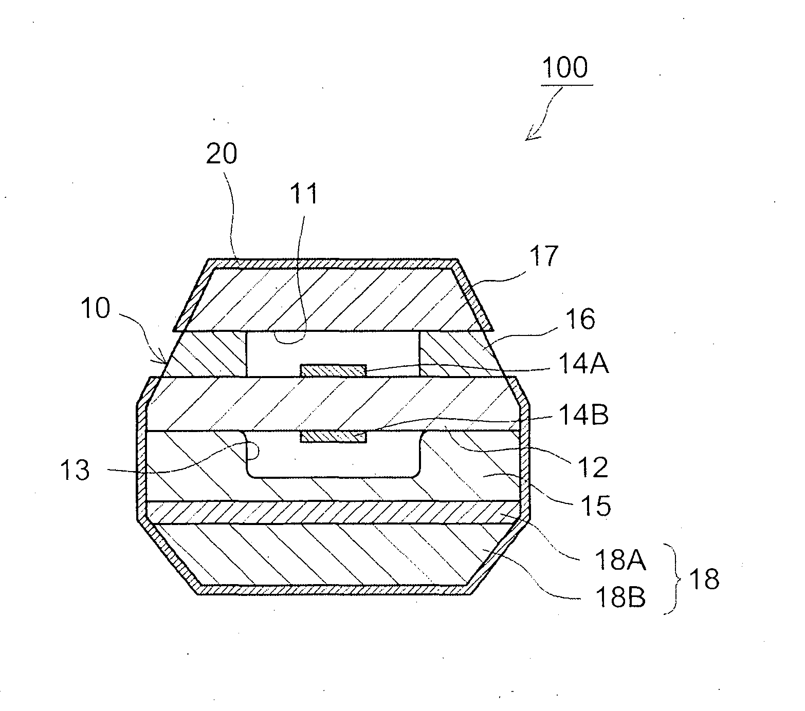
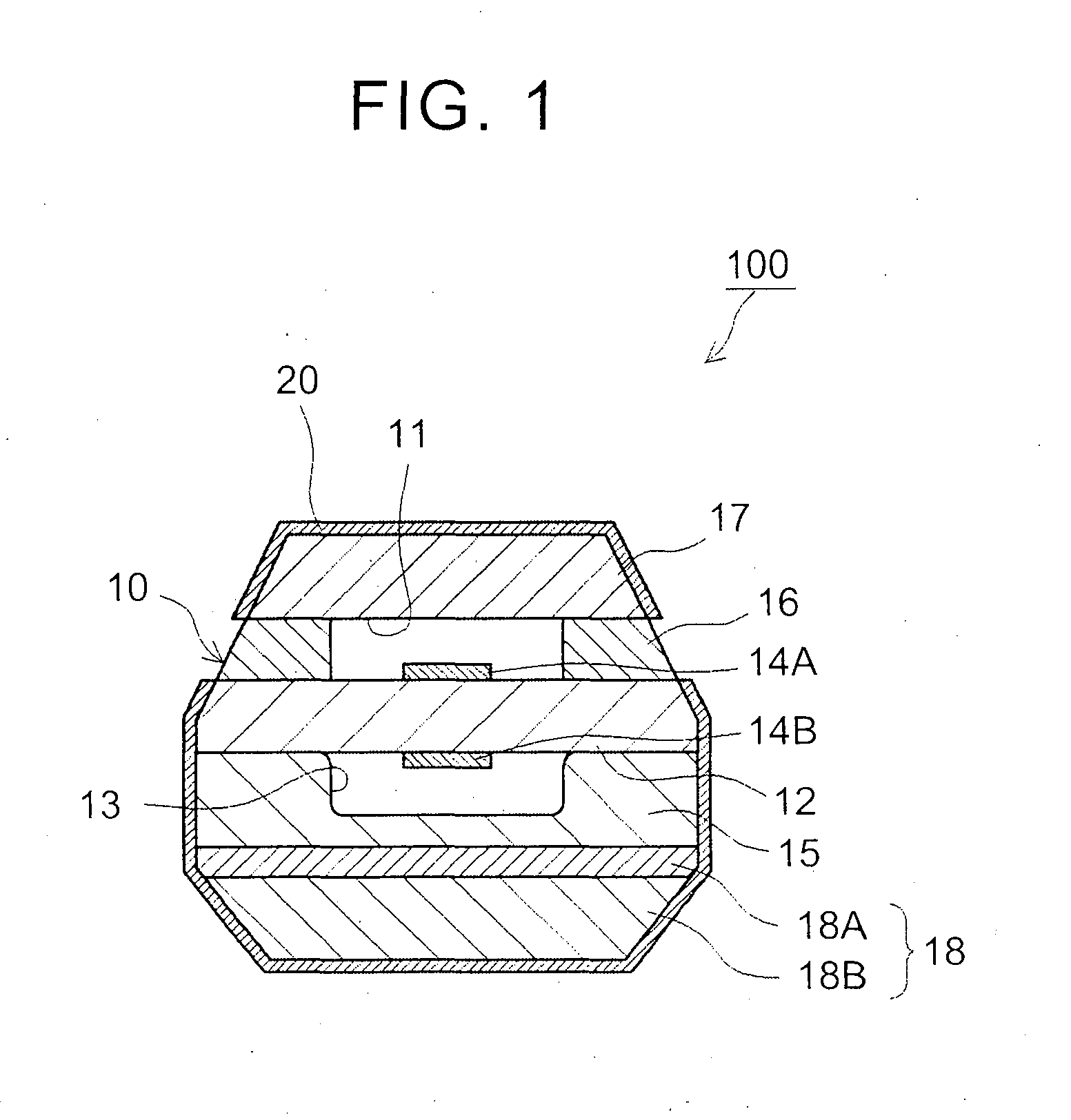
[0041]The measurement electrode 14A is formed outward of the solid electrolyte layer 12. A measurement gas space 11, into which exhaust gas can be introduced, and having, as one wall, the solid electrolyte layer 12, is formed further outward than measurement electrode 14A. The measurement gas space 11 is defined by the solid electrolyte layer 12, the diffusion resistance layer 16 and the shielding layer 17. The shielding layer 17 has a gas-impervious internal structure, and is made up of alumina in the The diffusion resistance layer 16 is provided at positions that define the measurement gas space 11 around the measurement electrode 14A (herein, at both ends of the measurement gas space 11 in the width direction), in order to restrict the introduction amount of exhaust gas into the measurement electrode 14A. The diffusion resistance layer 16 is a porous body through which exhaust gas is introduced into the measurement gas space 11. Materials that can make up a porous body, for inst...

second embodiment

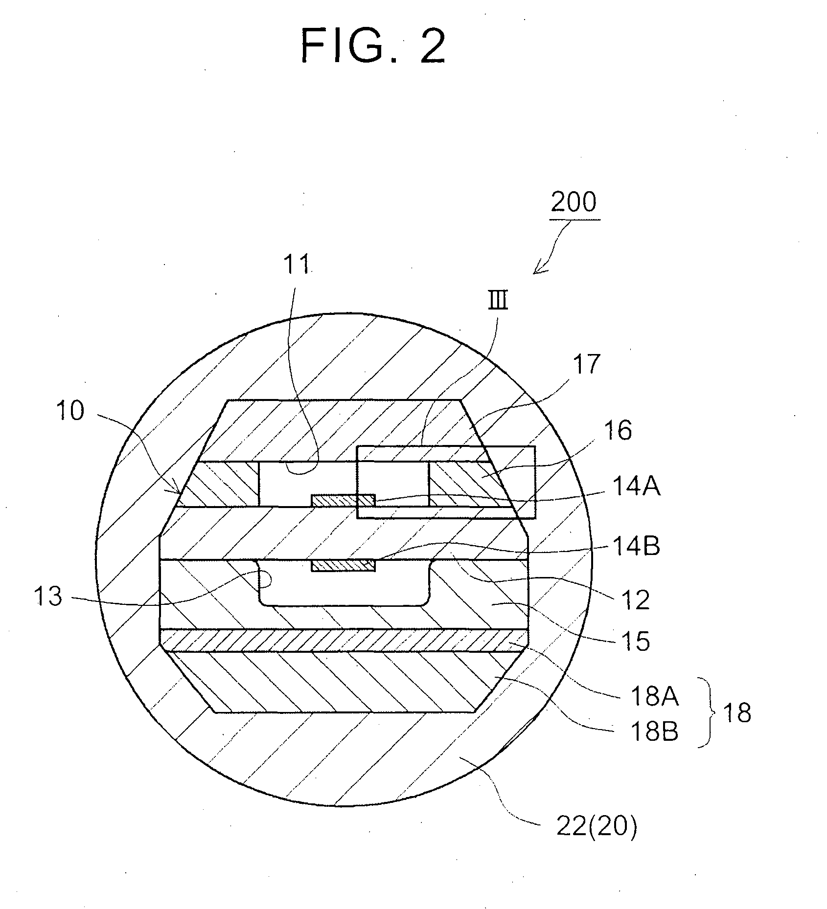
[0057]An explanation follows next, with reference to FIG. 2 and FIG. 3, on an exhaust gas sensor 200 according to the invention.

[0058]In the embodiment, a porous protective layer 22 is formed so as to cover the entire surface of the sensor element 10, as illustrated in FIG. 2. The porous protective layer 22 is made up of a porous body in which multiple ceramic particles are bonded to each other. The porous protective layer 22 is provided in order to suppress water breakage of the sensor element 10 by water that reaches the latter. The manganese reaction layer 20 is formed through addition, to the porous protective layer 22, of a substance that contains an element capable of generating a complex oxide having manganese (typically, a spinel-structure or perovskite-structure complex oxide having manganese).

[0059]FIG. 3 is a diagram illustrating an enlargement of region III in FIG. 2. As illustrated in FIG. 3, the porous protective layer 22 has ceramic particles 24. For instance, the cer...


PUM

PropertyMeasurementUnit
mass %aaaaaaaaaa
mass %aaaaaaaaaa
temperatureaaaaaaaaaa

Abstract

An exhaust gas sensor (100; 200) is configured so as to detect an oxygen concentration or air-fuel ratio in exhaust gas. The exhaust gas sensor includes a sensor element (10) and a manganese reaction layer (20). The sensor element detects an oxygen concentration or air-fuel ratio. The manganese reaction layer is formed on at least part of a surface of the sensor element and is formed of a substance containing an element capable of generating a complex oxide having manganese through reaction with a manganese oxide in the exhaust gas. The exhaust gas sensor is configured to detect an oxygen concentration or air-fuel ratio in exhaust gas of an internal combustion engine that utilizes a fuel having a Mn concentration in excess of 20 ppm.

Description

BACKGROUND OF THE INVENTION[0001]1. Field of the Invention[0002]The invention relates to an exhaust gas sensor.[0003]2. Description of Related Art[0004]Gas sensors that utilize sensor elements have been used conventionally in order to detect specific gases in the atmosphere. Such gas sensors, for instance, can detect the concentration of a specific gas component such as hydrocarbons (HC), oxygen (O2) or the like that are present in the exhaust gas of automobiles. To that end, one such gas sensor is provided in the exhaust passage of an internal combustion engine, for instance an automobile engine. The gas sensor is used to control an exhaust gas control apparatus. Conventional oxygen sensor elements that detect the concentration of oxygen in exhaust gas include, for instance, oxygen concentration-electromotive force sensors that have a ZrO2 solid electrolyte.[0005]As illustrated in FIG. 15, an oxygen sensor element 90, in the form of a bottomed cylinder, is configured through sequen...

Claims


Application Information

Patent Timeline
Patent Type & Authority Applications(United States)
IPC IPC(8): G01N27/409G01N27/407
CPCG01N27/409G01N27/4072G01N27/4077G01N27/4075G01N27/407
Inventor MIWA, TOMOHIROKAMIYA, SUMIOSAKAKIBARA, HIROTAKASHINMA, TOMOAKI
Owner TOYOTA JIDOSHA KK
Why Eureka
Try Eureka