Aircraft fuel systems

a fuel system and aircraft technology, applied in the direction of fuel tank safety measures, aircraft power plants, conditioning fuel arrangements, etc., can solve the problems of difficult monitoring of their effectiveness, energy loss to the compressed air supply, and cost-effective operation over their life cycle, so as to reduce heat load and therefore system cooling capacity, the effect of reducing the risk of damage and increasing the thermal mass

Inactive Publication Date: 2015-06-04
AERO SYST CONSULTANTS
View PDF16 Cites 31 Cited by
  • Summary
  • Abstract
  • Description
  • Claims
  • Application Information

AI Technical Summary

Benefits of technology

[0032]Aircraft fuel systems which incorporate a fuselage tank as a ‘feed tank’ which is normally maintained full, and supplies fuel directly to the aircraft engines, may also benefit from the addition of principles of the present invention. Such aircraft fuel system architectures may require a significantly reduced heat load (and therefore system cooling capacity) of the cooling loop as they will be less susceptible to heat addition by means of their increased thermal mass, and may have reduced or zero heat input from adjacent aircraft bays. Such system applications should be modified in their size and capacity to consider the reduced heat load, and may require minimal additional recirculated fuel cooling due to the fact that cooled fuel is recirculated to them through normal fuel sequencing. The present invention can in some embodiments augment the advantages of a fuselage feed tank architecture (such as maintaining them full thereby maximizing thermal mass) by reducing or removing heat sources in or adjacent to such tanks, and augmenting cooling flow from transfer tanks by recirculated cooled fuel as required.
[0033]The fuel cooling solutions of the present invention may also be further optimized by pre-cooling of uploaded fuel during refuelling. This may serve to decrease the cooling load and therefore the size of the fuel cooling system.
[0034]The fuel cooling solutions for center / fuselage tanks according to the present invention may also be further optimized when in combination with wing tanks with reduced cooling properties, by pressurizing the wing tanks to be higher than local ambient pressure, for example while at elevated altitudes. Such solutions may allow the cooling loop system size to be reduced such that the wing tanks require little or no cooling. Pressurization of the center tank at levels higher than local ambient while at elevated altitudes may similarly reduce the size and capacity of the cooling loop system.
[0035]The fuel tank floor of the ‘target’ tank, i.e. the tank to which cooled fuel is directed, or indeed any part of the target tank, may be cooled using a fluid other than fuel in the cooling loop. Tank cooling may be provided, for example and without limitation, by direct cold air venting, refrigerant, water / coolant mixture or hydraulic fluid. Such alternate cooling options may reduce the complexity of the cooling loop system for some aircraft types.

Problems solved by technology

Although effective, such inerting systems are often larger than desired, use on-board resources such as compressed air, and are costly to operate over their life cycle.
Such systems are also difficult to monitor their effectiveness, to assure an inert atmosphere in the space above the fuel.
This often results in the requirement for all of the tanks on such future aircraft platforms [including some aircraft programs currently in development] requiring inerting of all fuel tanks and not merely the fuselage mounted fuel tanks.
Such ‘all-tanks’ inerting systems are often large, have many air separation modules (ASMs), and use a lot of compressed air which results in energy being lost to the compressed air supply.
The overall cost of operation of such systems is therefore often unacceptably high.
Such inerting system solutions add significant weight and cost to the aircraft platform, and may significantly add to the operational costs of the aircraft due to reduced reliability and increased maintainability.

Method used


Image

  • Aircraft fuel systems
  • Aircraft fuel systems
  • Aircraft fuel systems

Examples


first embodiment

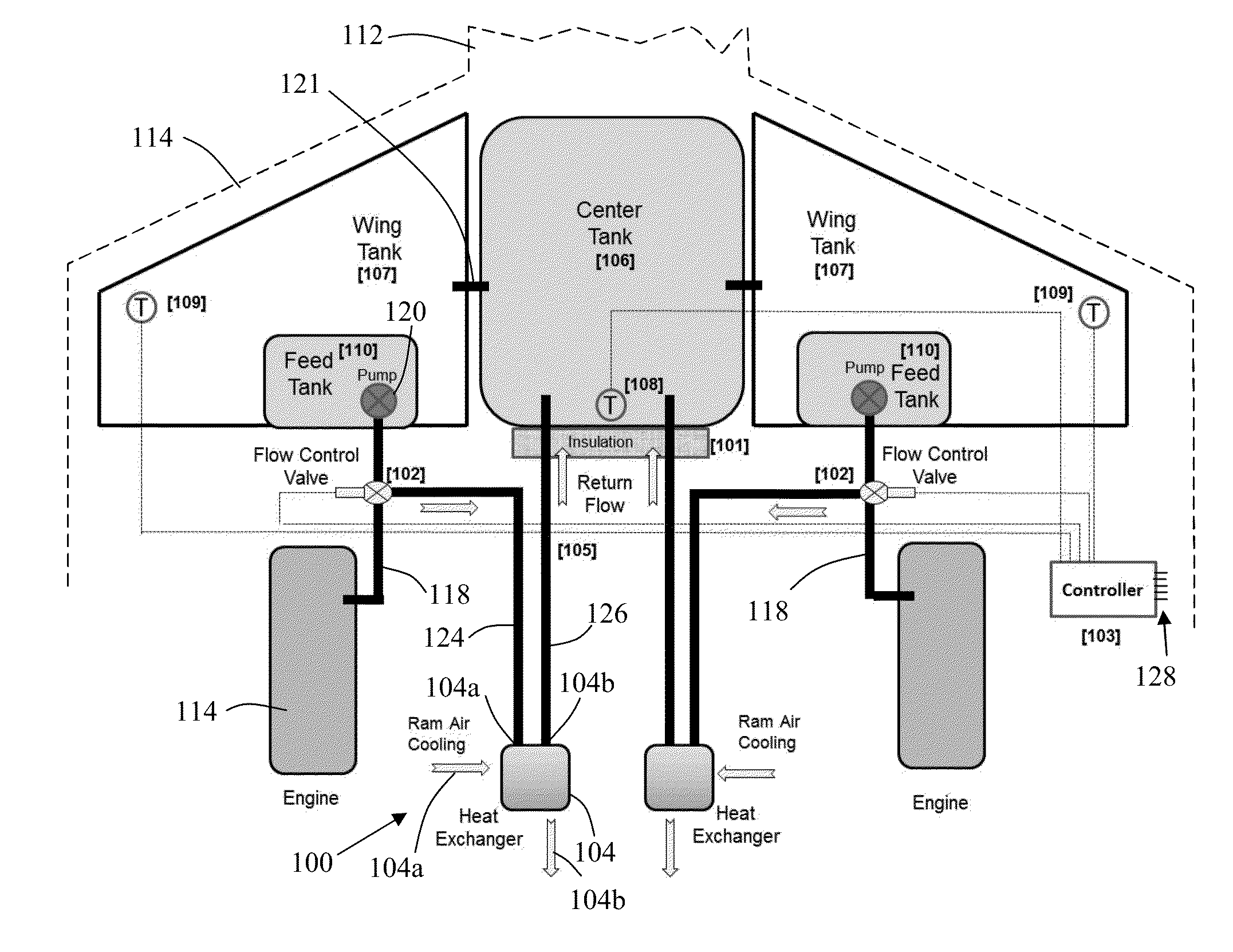
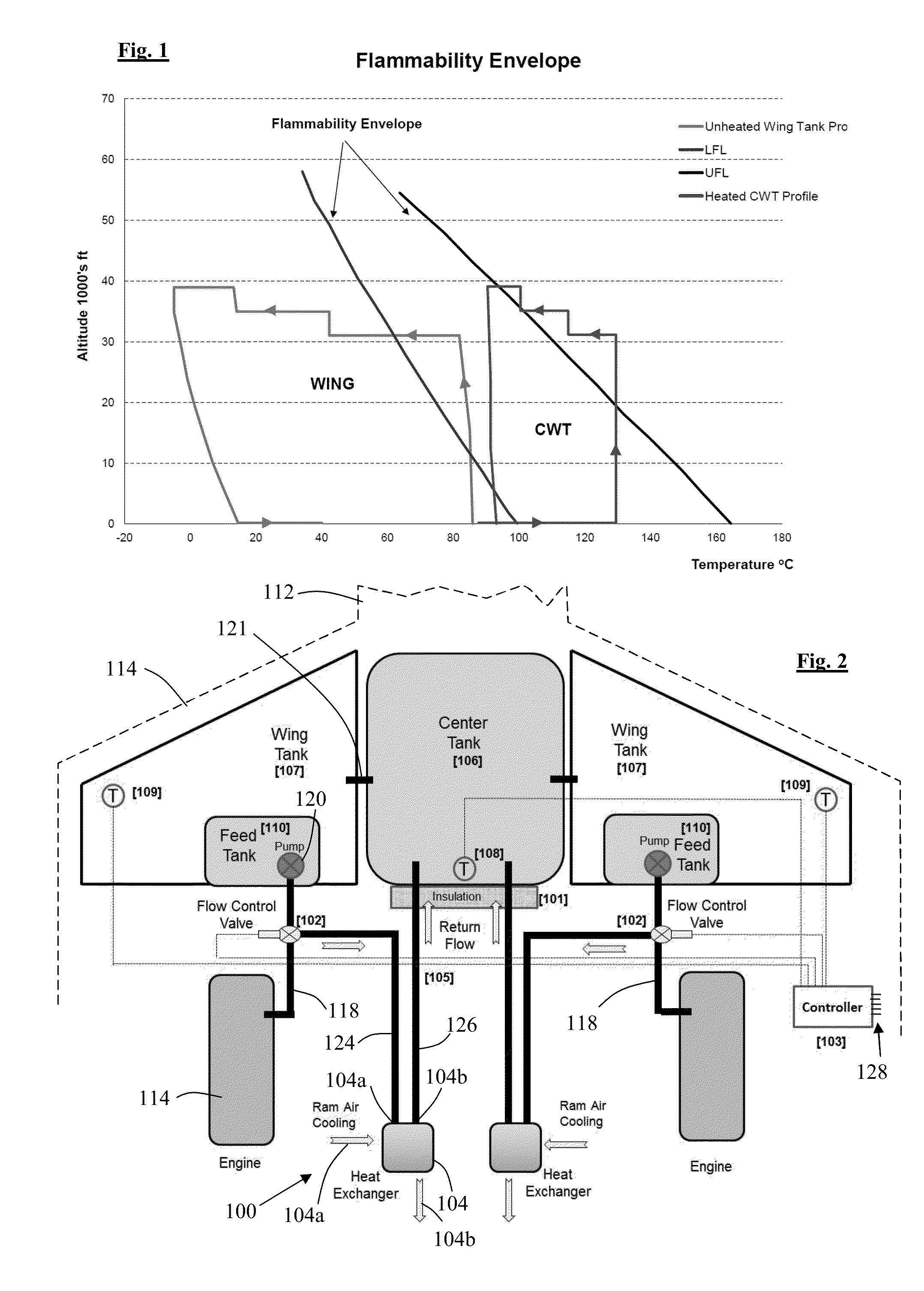
[0049]Referring to FIG. 2 according to the invention, fuel in an aircraft fuel system comprises a centre tank 106 located in the centre of the fuselage 112 of the aircraft and two wing tanks 107 each located in one of the wings 114 of the aircraft. A fuel feed tank 110 is located in each of the wing tanks 107, and each of two engines 116 is connected to a respective one of the fuel feed tanks 110 by a respective fuel feed pipe 118, and a pump 120 is provided in each of the fuel feed pipes 118 to pump fuel from the fuel feed tanks to the engines 116. Pipes 121 are provided interconnecting the tanks 106, 107, 110 of the fuel storage system in conventional manner to allow fuel to flow between them, using a conventional fuel transfer system not shown in the illustration.

[0050]A fuel cooling circuit 100 is provided on each side of the aircraft to cool the fuel in the storage system, in this case in the centre tank 106. Each cooling circuit comprises a heat exchanger 104 having an inlet 1...

third embodiment

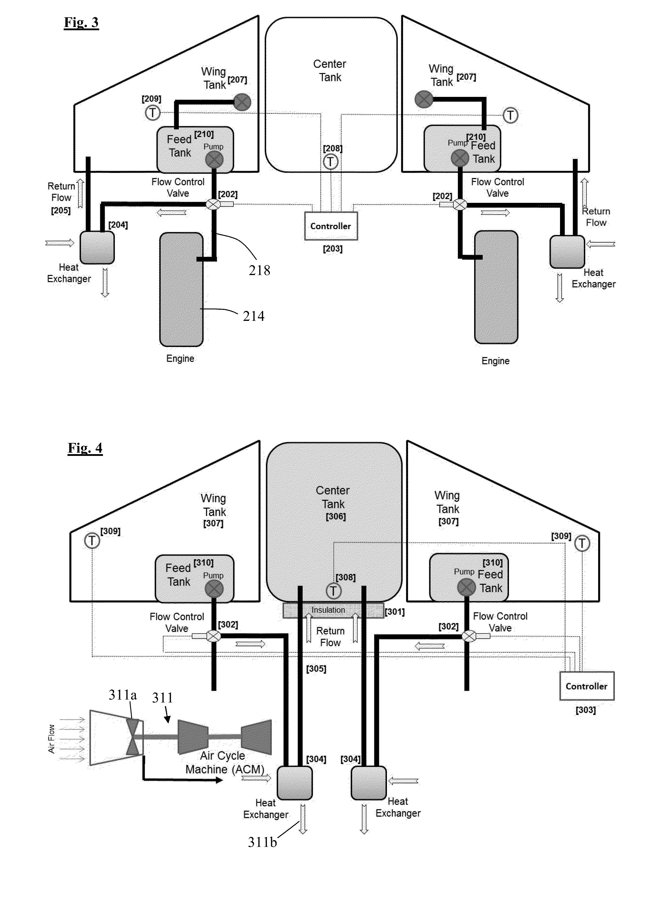
[0054]Referring to FIG. 4, a fuel system according to the present invention comprises an embodiment of the invention where fuel in an aircraft fuel tank is cooled to reduce its temperature below the flammability limit for the fuel being used, using cooling air flow from the aircraft air cycle machine inlet. Again, features of FIG. 4 corresponding to those of FIG. 2 are indicated by the same reference numerals increased by 200. Heat flow from high temperature bays which are adjacent to the fuel tank is minimized by use of insulation 301, in order to minimize the fuel cooling requirements of the present invention. Fuel flow is diverted from a tee in the fuel engine feed flow supply via a flow control valve 302, which allows the diverted fuel flow to be on or off. Control of the diverter valve is by means of a system controller 303. When valve 302 is commanded open, fuel flows to both the engine and the cooling loop of the present invention. When valve 302 is commanded closed, fuel con...

fourth embodiment

[0055]the present invention will now be described with reference to FIG. 5, and comprises an embodiment of the invention where fuel in an aircraft fuel tank is cooled to reduce its temperature below the flammability limit for the fuel being used, using cold air from the aircraft Environmental Control System (ECS) 411. The ECS is arranged to condition air that is circulated to the passenger area of the aircraft and therefore air within it is typically significantly cooler than the target temperature of the fuel tanks. Again, features of FIG. 5 corresponding to those of FIG. 2 are indicated by the same reference numerals increased by 300. Heat flow from high temperature bays which are adjacent to the fuel tank is minimized by use of insulation 401, in order to minimize the fuel cooling requirements of the present invention. Fuel flow is diverted from a tee in the fuel engine feed flow supply via a flow control valve 402, which allows the diverted fuel flow to be on or off. Control of ...


PUM


Abstract

Aircraft fuel system reduces flammability exposure of fuel tanks. In one embodiment, aircraft center fuel tank fuel is cooled in flight to reduce flammability exposure to be similar to that of an unheated metal wing tank. Fuel tanks having adjacent heat sources are insulated to minimize heat flow into the fuel. Fuel tanks having lower cooling properties, e.g., composite wing tanks, are cooled during flight so temperatures are reduced to be similar to metal wing tanks. A fuel tank, pressurized relative to outside pressure at altitude, having lower flammability exposure than unpressurized tanks and cooling fuel in the tank reduces flammability exposure of the fuel tank to be similar to that of an unpressurized metal wing tank. Recirculating flow from a tank, passing through heat exchanger, and returning to the tank cools fuel. A controller starts/stops fuel flow to tanks and uses sensors to command flow to reduce flammability.

Description

FIELD OF THE INVENTION[0001]The present invention relates to aircraft fuel systems, and in particular to systems for improving aircraft safety and reduce aircraft vulnerability due to fuel tank flammability. It mainly has application in commercial aircraft.BACKGROUND TO THE INVENTION[0002]There is an increasing need for aircraft fuel tank flammability reduction solutions, primarily for commercial aircraft to comply with fuel tank flammability reduction regulations. These regulations describe requirements to make commercial aircraft fuel tank flammability exposure equivalent to unheated conventional aluminium wing tanks, on a fleet-wide average basis.[0003]Contemporary commercial aircraft incorporate fuel tank inerting systems or in-tank oxygen reduction methods to reduce the flammability exposure of their fuel tanks on a fleet-wide average basis. This resulted from regulations developed by the Federal Aviation Administration (FAA), European Aviation Safety Agency (EASA) and other re...

Claims


Application Information

Patent Timeline
Patent Type & Authority Applications(United States)
IPC IPC(8): B64D37/32B64D37/02B64D37/00
CPCB64D37/32B64D37/02B64D37/005B64D37/04B64D37/34
Inventor JONES, PHILIP E.
Owner AERO SYST CONSULTANTS
Why Eureka
Try Eureka