System and method of cooling of photovoltaic panel and method of installation of system

a photovoltaic panel and cooling system technology, applied in photovoltaics, lighting and heating apparatus, electrical apparatus, etc., can solve the problems of inapplicability, contradictory cell temperature requirements, and inability to achieve the effect of cooling,

Inactive Publication Date: 2015-06-04
MASARYK MICHAL
View PDF0 Cites 11 Cited by
  • Summary
  • Abstract
  • Description
  • Claims
  • Application Information

AI Technical Summary

Problems solved by technology

This solution is not practical due to high water consumption.
However, this kind of configuration lays down contradictory requirements on the cell temperature.
In case of separately standing power plants, the heat obtained from photovoltaic panels is basically unexploitable since there is no place to which the heat can be

Method used


Image

  • System and method of cooling of photovoltaic panel and method of installation of system
  • System and method of cooling of photovoltaic panel and method of installation of system
  • System and method of cooling of photovoltaic panel and method of installation of system

Examples


examples of invention implementations

Example 1

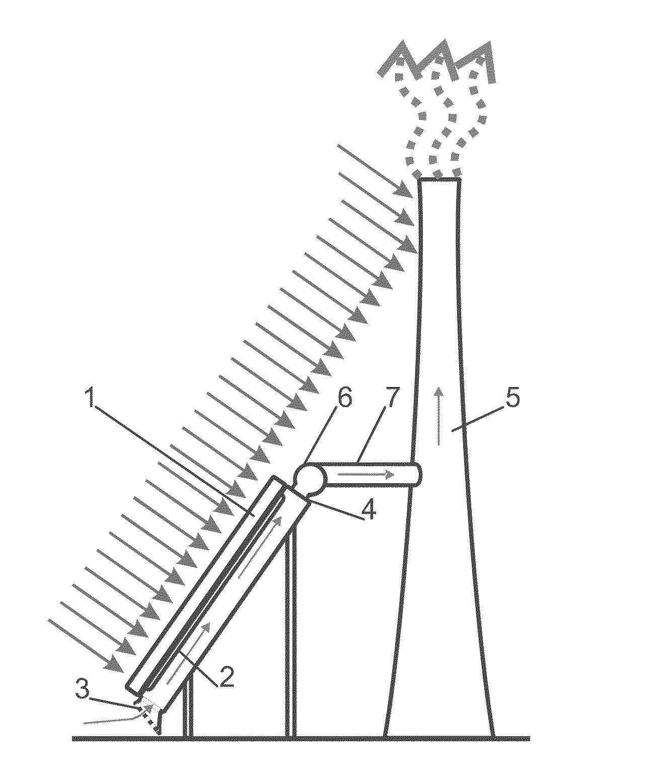
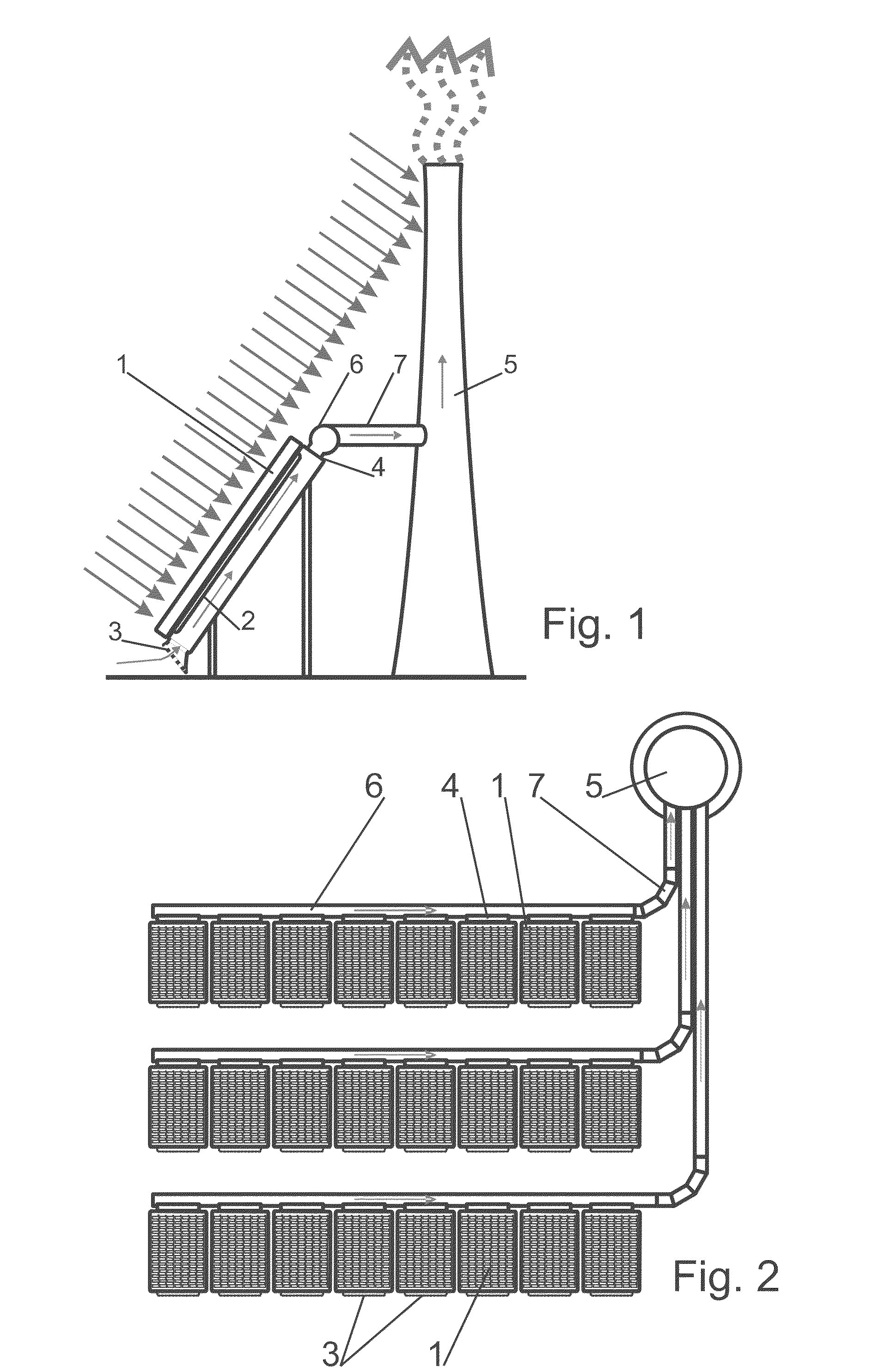
[0050]In the example according to the FIGS. 1, 2 and 6, there is a cooling system and method used in a small photovoltaic power plant that has three rows of panels 1 with 8 panels 1 in each row. Each panel 1 encompasses a unit, in which there are air coolers 2. The air coolers 2 are in the form of aluminium grille ribs at the back side of the photovoltaic cells. In the lower part of the unit there is a cooling air intake opening 3, in the upper part at the back there is an air outtake vent 4. The cooling air intake opening 3 is equipped with a mesh net preventing insects from entering the unit.

[0051]The unit outtake vent 4 is connected to a joint thermal collector 6 for one row of panels 1. Each of the three collectors 6 is then connected to a chimney 5 using independent and different diameter warm air piping 7. The pipework forming warm air piping 7 of the first and second order is transparent and runs on the eastern side.

[0052]A chimney 5 is in the north-eastern corner of...

example 2

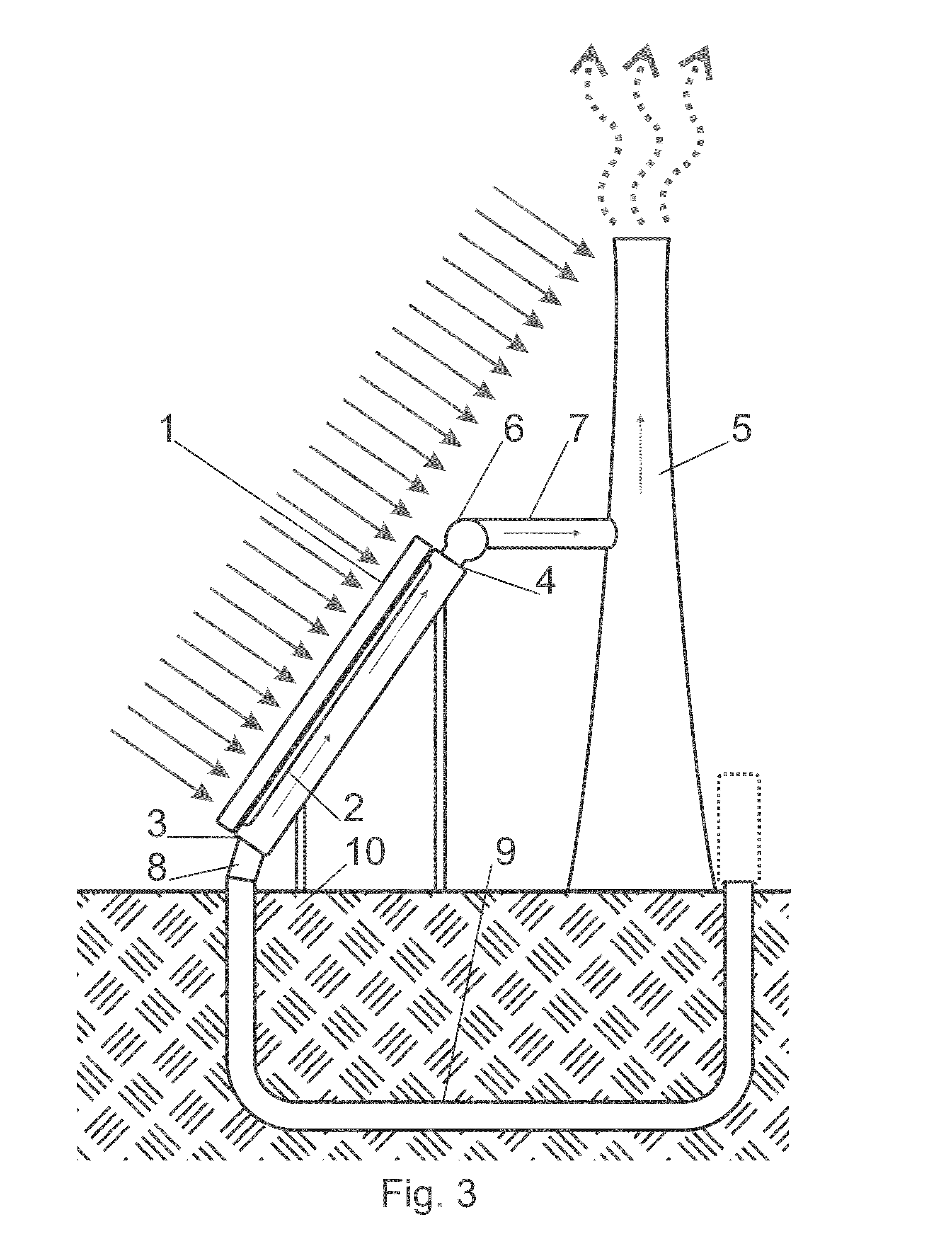
[0053]In the example according to the FIGS. 3 and 4, the system described in the previous example is supplemented for a ground-coupled heat exchanger 9 of the air—ground 10 type. The ground-coupled heat exchanger 9 consists of several 6 m long plastic pipes of 400 mm diameter. The pipes are connected using pipe fittings forming a 60 m long route, in which the sucked air is cooled. The cooling air piping 8 connects the intake openings 3 with the ground-coupled heat exchanger 9.

[0054]The ground-coupled heat exchanger 9 is under ground 10 under photovoltaic panels 1. It was dug into the ground 10 even before the photovoltaic panels 1 were mounted. The air intake into the ground-coupled heat exchanger 9 is above the ground level on the north side and it is equipped with a replaceable filter.

example 3

[0055]In the example according to the FIG. 5, there is a ground-coupled heat exchanger 9 in the form of a register, in which air flow division are reached and by that even the speed and pressure losses are lowered. In principle, it is possible to use various combinations of ground-coupled heat exchanger 9 installation.


PUM


Abstract

A heat is taken from a photovoltaic panel (1) using air that flows through the photovoltaic panel (1) unit with an air cooler (2). The unit has an air intake opening (3) and an outtake vent (4) and the air flow is enforced by a natural draft of a chimney (5), to which the photovoltaic panel (1) unit is connected to. At least a part of the chimney (5) is exposed to solar radiation. Outtake vents (4) of several photovoltaic panel (1) units can lead to one chimney (5), preferably through thermal collectors (6) and piping. The air in the chimney is warmed up by solar radiation, the air ascends towards the chimney (5) mouth and the chimney (5) natural draft created in this way enforces air flow within the photovoltaic panel (1) unit. Even the air cooler (2) of the sucked air can form part of the system—preferably in the form of a ground-coupled heat exchanger (9). The chimney (5) can be equipped with heat-absorbing surface and it can also have a supporting wind device transforming wind energy into a natural draft within the chimney (5).

Description

CROSS REFERENCE TO RELATED APPLICATION[0001]This application is a national stage entry of PCT / IB2013 / 054617 filed Jun. 5, 2013, under the International Convention claiming priority over Slovakia Patent Application No. PUV50051-2012 filed Jun. 5, 2012 and Slovakia Patent Application No. PUV50060-2013 filed Jun. 5, 2013.FIELD OF THE INVENTION[0002]The invention refers to a cooling system and a cooling method of a photovoltaic panel, which is being cooled in order to reach higher efficiency of its cells. The cooling system is energetically independent from the surrounding environment and the cooling effect is proportionate to the amount of incident solar radiation. The invention also describes the method of system installation.BACKGROUND OF THE INVENTION[0003]The efficiency of photovoltaic cells and panels, above all the ones made from silicon, depends on the temperature; specifically, with growing temperature of a photovoltaic cell its efficiency decreases. The decrease in efficiency ...

Claims


Application Information

Patent Timeline
IPC IPC(8): H02S40/42F16L1/028
CPCF16L1/028H02S40/425F24S10/00F24S90/10F24T10/10F24T10/30F24T10/40F28D20/0052H01L31/0521H02S40/44Y02E10/10Y02E10/44Y02E10/46Y02E10/50Y02E10/60Y02E60/14Y02E70/30
Inventor MASARYK, MICHAL
Owner MASARYK MICHAL
Why Eureka
Try Eureka