Current detection device

a current detection and detection device technology, applied in the direction of measurement devices, current measurements only, instruments, etc., can solve the problems of affecting difficult downsizing of conventional examples, and affecting so as to improve the stability of overcurrent and the accuracy of current detection. , the effect of reducing the size of conventional examples

Inactive Publication Date: 2015-06-11
PANASONIC INTELLECTUAL PROPERTY MANAGEMENT CO LTD
View PDF5 Cites 3 Cited by
  • Summary
  • Abstract
  • Description
  • Claims
  • Application Information

AI Technical Summary

Benefits of technology

[0021]The current detection device according to the present invention includes: the magnetic flux detection unit configured to detect the magnetic flux generated in the core due to the current flowing through the conductor; and the adder unit configured to add a feedback signal to the excitation signal such that the magnetic flux

Problems solved by technology

However, there is a problem in that the conventional example described in Document 1 has a complicated structure and downsizing thereof is difficult, since the transformer is constituted by two cores (the probe core and the compensation core) and two windings (the probe winding and the compensation winding).
Also, there is a problem in that, although the magnitude of AC current flowing through

Method used


Image

  • Current detection device
  • Current detection device
  • Current detection device

Examples


Embodiment Construction

[0030]Hereinafter, embodiments of a current detection device according to the present invention will be described in detail with reference to the diagrams.

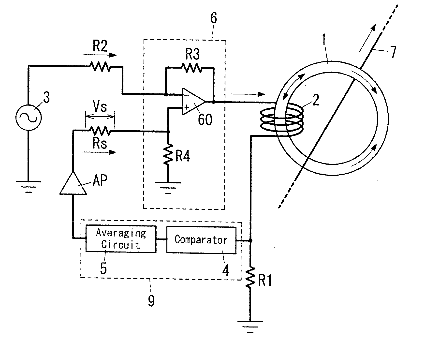
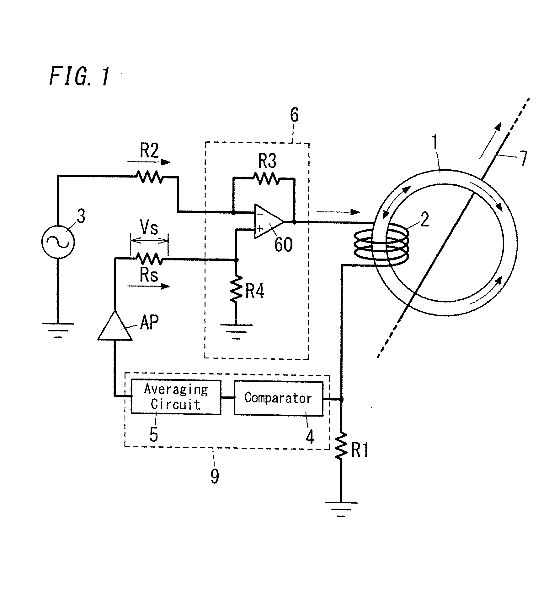
[0031]The current detection device according to one embodiment includes a core 1, a winding 2 that is wound around the core 1, an excitation unit 3, a comparator 4, an averaging circuit 5, an adder unit 6, and the like, as shown in FIG. 1.

[0032]The core 1 is formed of soft magnetic material in a circular ring shape through which a conductor 7, as a detection target, passes. The soft magnetic material that forms the core 1 is preferably nanocrystal material, amorphous metal material (such as amorphous ribbon or amorphous wire), ferrite, magnetic fluid, or the like. The nanocrystal material and the amorphous metal material have an advantage that a hysteresis loop is maintained up to a high frequency, and the amorphous metal material is superior in strength over the nanocrystal material. Also, the ferrite has a feature that the cost ...


PUM


Abstract

A current detection device includes: a core to be disposed in the vicinity of a conductor as a detection target; a winding wound around the core; an excitation unit configured to apply an excitation signal, having a magnitude and a direction that change at a constant period, to the winding; a magnetic flux detection unit (comparator and averaging circuit) configured to detect a magnetic flux generated in the core due to current flowing through the conductor; and an adder unit configured to add a feedback signal to the excitation signal such that the magnetic flux detected by the magnetic flux detection unit is cancelled.

Description

TECHNICAL FIELD[0001]The invention relates to a current detection device configured to detect current flowing through a conductor in a contactless manner.BACKGROUND ART[0002]JP 2004-523909A (hereinafter referred to as Document 1) describes one kind of current detection devices. A conventional example described in Document 1 includes a transformer that has a probe core, a probe winding, a compensation core, a compensation winding, and the like. The probe winding is wound around the ring-shaped probe core, and the compensation winding is wound around both the probe core and the ring-shaped compensation core having a diameter larger than that of the probe core. A conductor, which is a measurement target, is disposed so as to pass through the probe core and the compensation core.[0003]In this conventional example, the magnitude of current flowing through the conductor is detected by a known flux gate detection circuit. That is, this detection circuit includes a symmetry stage and an amp...

Claims


Application Information

Patent Timeline
IPC IPC(8): G01R19/00G01R33/06
CPCG01R33/06G01R19/0092G01R15/185G01R15/186G01R15/18G01R19/165
Inventor YOSHIDA, HIROSHIKANDA, MASATAKAKAGAWA, TAKUYAOKADA, KENJINAKAMURA, ATSUSHI
Owner PANASONIC INTELLECTUAL PROPERTY MANAGEMENT CO LTD
Why Eureka
Try Eureka