Plant for energy production

Active Publication Date: 2015-06-18
NEST
View PDF3 Cites 53 Cited by
  • Summary
  • Abstract
  • Description
  • Claims
  • Application Information

AI Technical Summary

Benefits of technology

[0020]Be easy to integrate within and modify existing facilities a

Problems solved by technology

This technology has some severe disadvantages in that it involves using very expensive storage fluids such as molten salt, it requires multiple oil/salt heat exchangers, it needs at least two large molten salt storage tanks, it requires molten salt pumps and corresponding pumping energy to move the mo

Method used


Image

  • Plant for energy production
  • Plant for energy production
  • Plant for energy production

Examples


Example

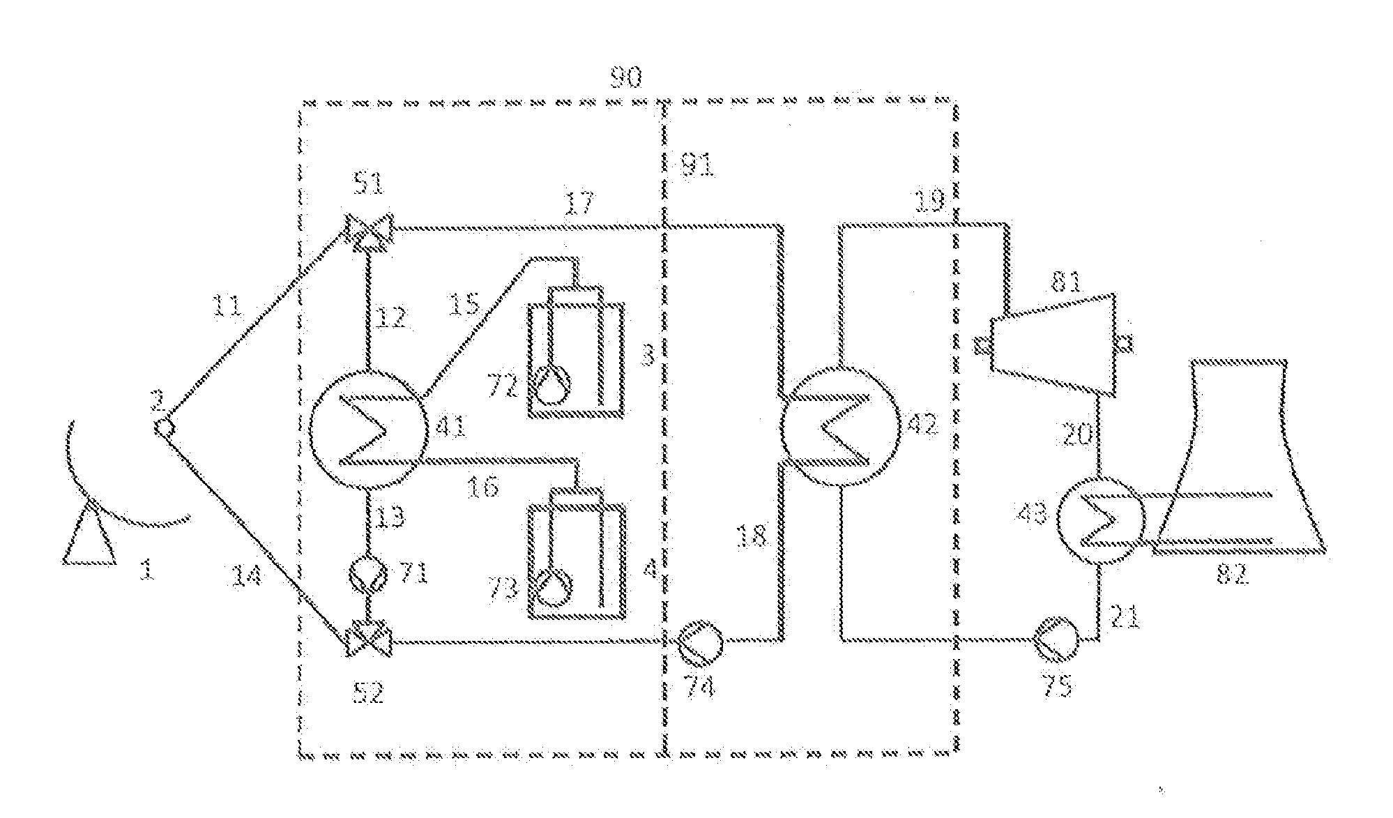
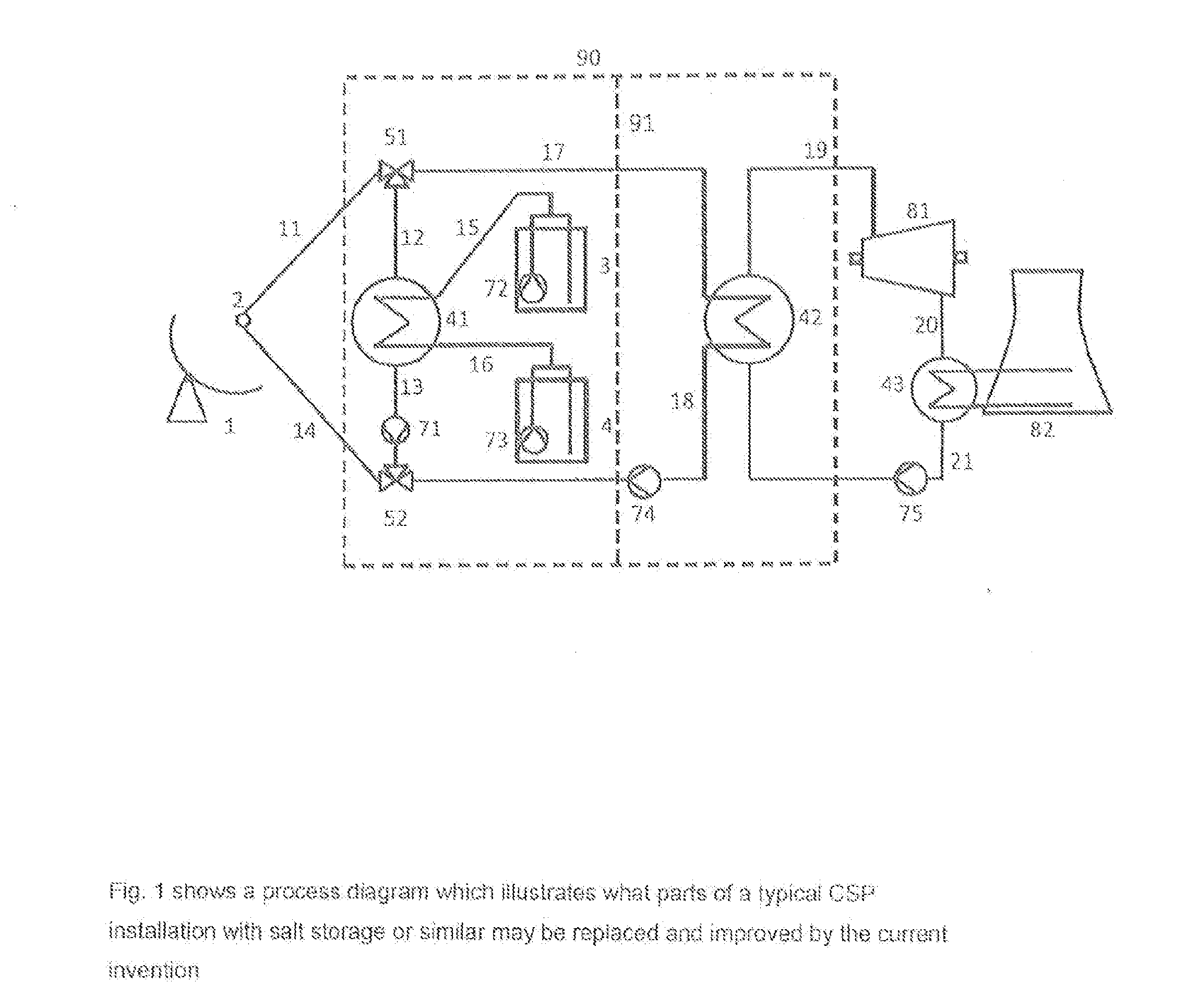
[0058]FIG. 1 illustrates one type of target application of the invention; this figure shows a schematic process diagram for a prior art parabolic, trough type, concentrated solar power installation not according to the invention. A purpose of this figure is to illustrate the complexity of such conventional CSP plants and to show how the system can be greatly simplified and major parts of the system can be replaced by the current invention. In heat storing mode trough type parabolic mirrors 1 heat up oil in receiver 2 through which oil is pumped into pipe 11 into a valve 51 and from there into pipe 12, after which the oil goes into a heat exchanger 41 to deliver heat, after this the cooled oil is pumped by pump 71 through pipes 13 and 14 back into the trough heat absorber 2 for renewed heating. This pipe loop represents the primary heating loop; the working fluid in such a loop is typically thermal oil that can sustain high temperature whereas other working fluids may also be conside...


PUM


Abstract

The invention provides a plant for production of energy, comprising any type of heat or energy source including but not limited to solar power sources, nuclear reactors, fossil fuel plants, wind power plants, tidal power plants, waste heat power plants and geothermal sources, operatively arranged at an input side of the plant, and heat delivery or energy production means such as turbine-electric generator sets, operatively arranged at a delivery side of the plant. The plant is distinctive in that it further comprises a thermal energy storage with integrated heat exchanger, comprising a solid state thermal storage material, a heat transfer fluid and means for energy input and output, wherein: the storage comprises at least one heat transfer container, solid state thermal storage material is arranged around the heat transfer container, the heat transfer container contains the heat transfer fluid and the means for energy input and output, so that all heat transferring convection and conduction by the heat transfer fluid takes place within the respective heat transfer container, the thermal energy storage with heat exchanger has been arranged inside thermal insulation, and the solid state thermal energy storage with heat exchanger, has been arranged between the input side and delivery side of the plant for storage and heat exchange of thermal energy, the storage is coupled directly or via an additional heat exchanger to the source and the storage is coupled directly or via an additional heat exchanger to the delivery side of the plant.

Description

FIELD OF THE INVENTION[0001]The present invention relates to plants for production of energy from sources like solar power, particularly concentrated solar power (CSP) plants, but also from other thermal energy sources including but not limited to nuclear reactors, fossil fuel plants and deep earth geothermal sources. More specifically, the invention relates to modification of existing plant designs or for building simpler and more effective new plants.BACKGROUND OF THE INVENTION AND PRIOR ART[0002]Significant research and development efforts are being made on an international scale to improve the efficiency and environmental performance for energy producing systems. Today about half of all such efforts are made within the renewable energy sector rather than for traditional fossil or nuclear fuel type thermal power production. It has become clear that energy storage will be a key technology for making further advances, and large investments are currently being made in developing suc...

Claims


Application Information

Patent Timeline
IPC IPC(8): F03G6/06F24J2/34F24S23/00
CPCF24J2/34F03G6/06Y02E10/44Y02E70/30Y02E10/10F28D20/0056F28D2020/0065F03G6/065F03G6/067F03G7/04Y02E10/46F24S23/00F24S60/30Y02E60/14Y02P90/50F03G6/068F03G4/063
Inventor BERGAN, PAL
Owner NEST
Why Eureka
Try Eureka