Structure of power transmission apparatus

a technology of power transmission apparatus and structure, which is applied in the direction of engine starters, machines/engines, and gears, etc., can solve the problems of increasing the production cost of the power transmission system, time lag in cranking the internal combustion engine, and the tension of the endless transmitting member is great, so as to reduce the amount of time, avoid the effect of increasing the degree of tension, and minimize the loosening of the bel

Active Publication Date: 2015-06-18
DENSO CORP
View PDF6 Cites 21 Cited by
  • Summary
  • Abstract
  • Description
  • Claims
  • Application Information

AI Technical Summary

Benefits of technology

[0010]It is therefore an object to provide an improved structure of a power transmission system designed to minimize a time interval between issuing of a request to start an internal combustion engine and an actual start of the internal combustion engine.
[0011]According to one aspect of the invention, there is provided a power transmission system which works to transmit power, as produced by an internal combustion engine, to a first auxiliary device and a second auxiliary device. The first auxiliary device is operable either in a motor mode or in a regenerative mode. The power transmission system comprises: (a) a driving pulley which is joined to a drive shaft of the internal combustion engine to be rotatable along with rotation of the drive shaft; (b) a first auxiliary device pulley which is joined to a shaft of the first auxiliary device to be rotatable along with rotation of the shaft of the first auxiliary device; (c) a second auxiliary device pulley which is joined to a shaft of the second auxiliary device to be rotatable along with rotation of the shaft of the second auxiliary device; (d) an endless transmitting member which is wound around the driving pulley, the first auxiliary device pulley, and the second auxiliary device pulley; (e) a first auto-tensioner equipped with a first tensioner pulley which is rotatable in contact with the endless transmitting member, the first tensioner pulley being also movable relative to the internal combustion engine to change or regulate a degree of tension of the endless transmitting member; and (f) a controller which works to control an operation of the first auxiliary device. The controller actuates the first auxiliary device to move the first tensioner pulley to a given position prior to issuing of a start request to start the internal combustion engine, thereby minimizing the loosening of the belt between the driving pulley and the first auxiliary device pulley in the motor mode.
[0012]Prior to the issuing of the start request to start the internal combustion engine, the controller actuates the first auxiliary device in the motor mode to move the first tensioner pulley to the given position. Upon the issuing of the start request for the internal combustion engine, the first tensioner pulley, thus, lies at the given position, so that the degree of tension of the endless transmitting member between the driving pulley and the first auxiliary device pulley is higher than or equal to a required value. The actuation of the first auxiliary device as a starter in the motor mode to produce torque great enough for cranking the internal combustion engine upon the issuing of the start request, therefore, enables the drive shaft to be rotated immediately within a required period of time to crank the internal combustion engine. This achieves a quick start of the internal combustion engine and results in a decrease in amount of time between the issuing of the start request for the internal combustion engine and the actual start of the internal combustion engine.

Problems solved by technology

The power transmission system of the above publication is engineered to start operating the given accessory in the motor mode after it is required to start the internal combustion engine, thus taking time for the pulley of the first auto-tensioner to reach the limit of the relative movable range, thus resulting in a time lag in cranking the internal combustion engine.
Therefore, when the driving pulley and the pulley of the first auto-tensioner are started to be rotated suddenly by the pulley of the given accessory after they are stopped or when running at low speeds, the inertia thereof may result in a great increase in tension of the endless transmitting member.
This requires the need for making the endless transmitting member of material resistant to such a degree of tension, which will lead to an increase in production cost of the power transmission system.
The power transmission system also faces the drawback in that when it is instructed to operate the given accessory in the motor mode after issuing of a request to start the internal combustion engine, it will result in a lag in producing a field current in the given accessory, thus leading to a delay in starting the given accessory in the motor mode.
This also results in an increased lag in starting the internal combustion engine.

Method used


Image

  • Structure of power transmission apparatus
  • Structure of power transmission apparatus
  • Structure of power transmission apparatus

Examples


first embodiment

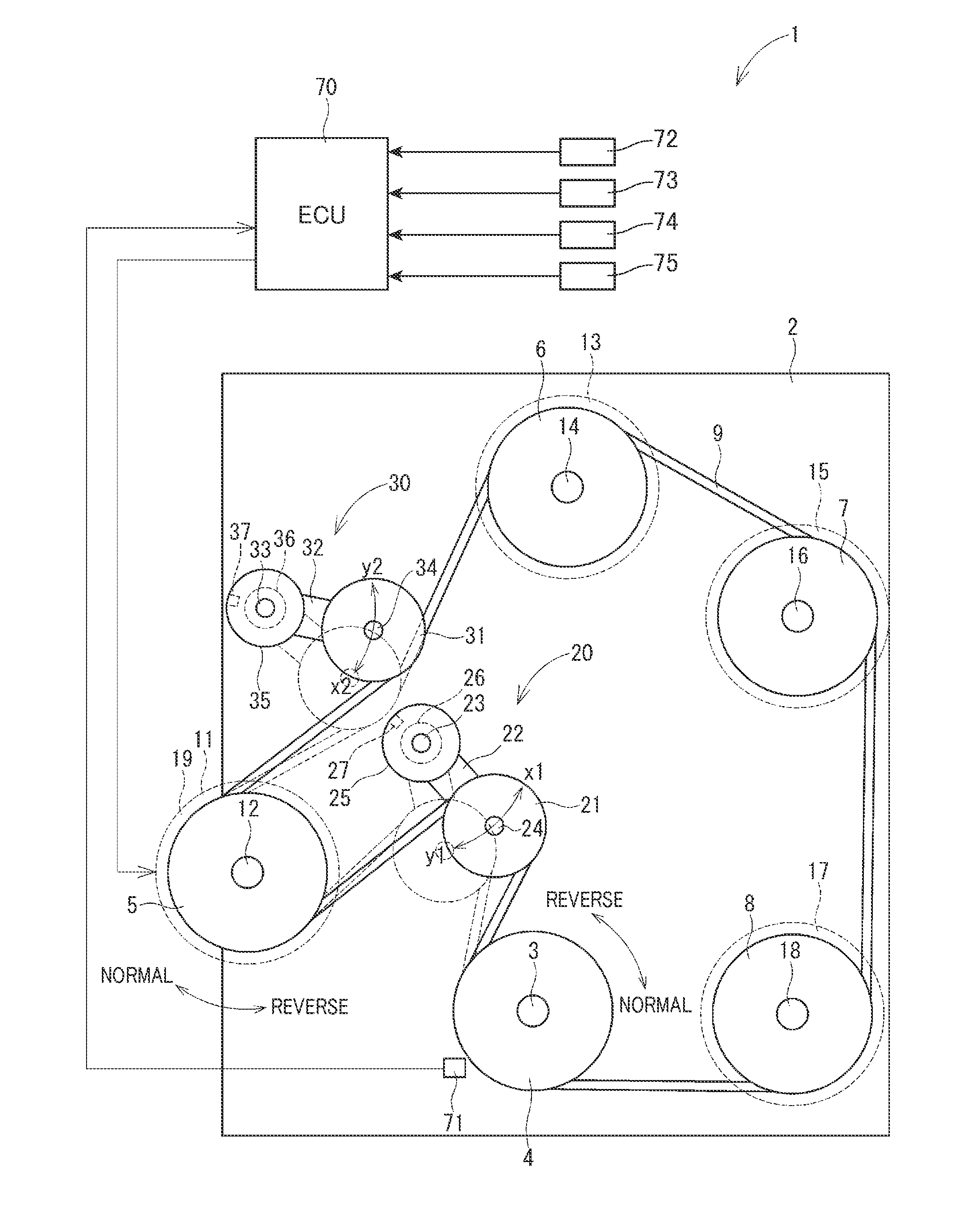
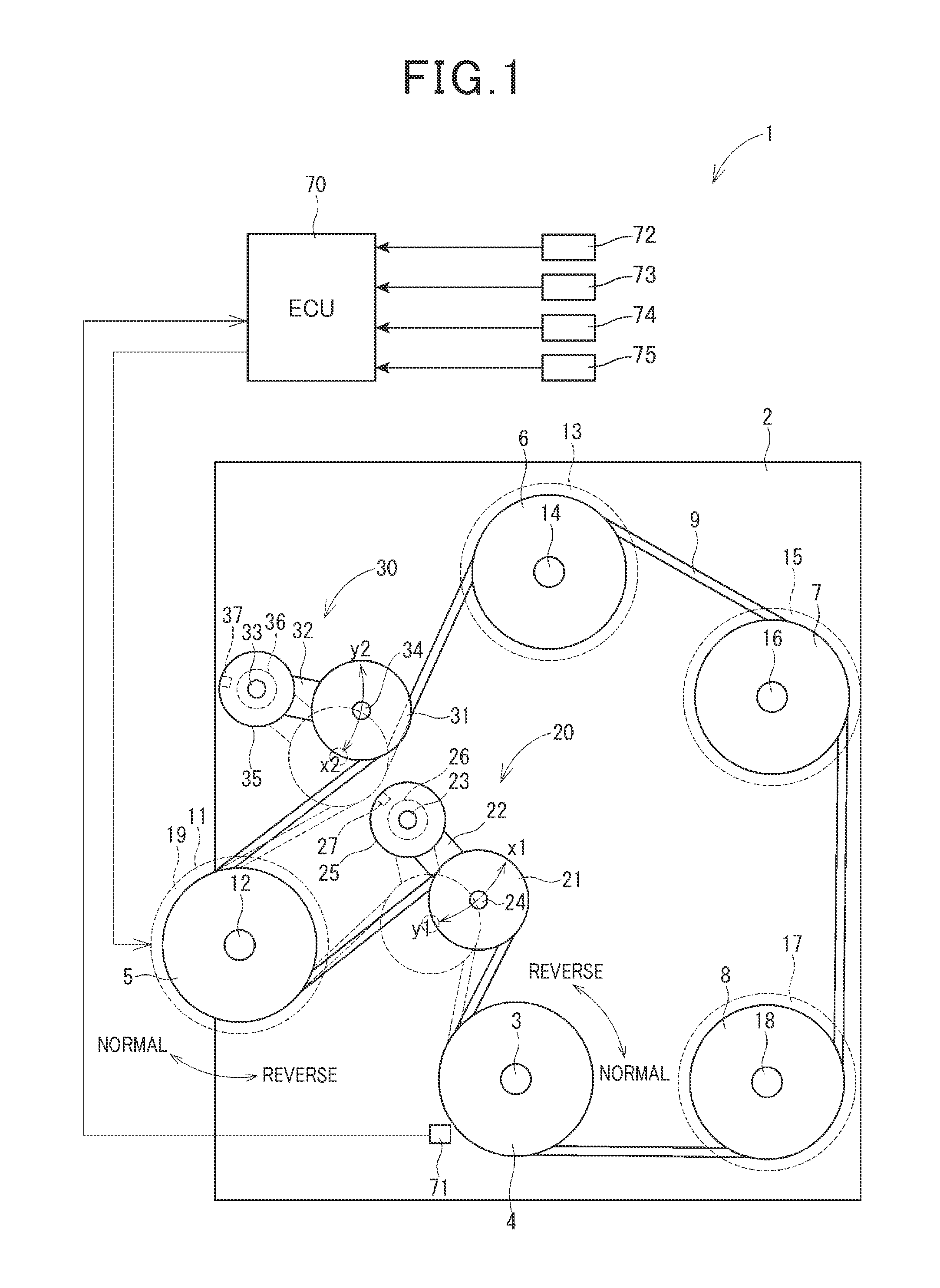
[0037]FIG. 1 illustrates a power transmission system 1 according to the first embodiment. The power transmission system 1, as referred to herein, is installed in an automotive vehicle equipped with an internal combustion engine 2 and works to transmit output power (i.e., torque), as produced by the engine 2, to a given accessory 11 and other accessories 13, 15, and 17 mounted in the vehicle. The accessories 11, 13, 15, and 17, as referred to herein, are auxiliary electric or mechanical devices which are supplied with or transmit power or torque from or to the internal combustion engine 2. The given accessory 11 will also be referred to below as a first auxiliary device. The accessories 13, 15, and 17 will also be referred to below as second auxiliary devices.

[0038]The power transmission system 1 is, as clearly illustrated in FIG. 1, disposed near the engine 2. The power transmission system 1 includes a driving pulley 4, a given accessory pulley 5, accessory pulleys 6, 7, and 8, a be...

second embodiment

[0084]FIG. 4 illustrates the power transmission system 1 according to the second embodiment which is different only in structure of the first auto-tensioner 20 and the second auto-tensioner 30 from the first embodiment.

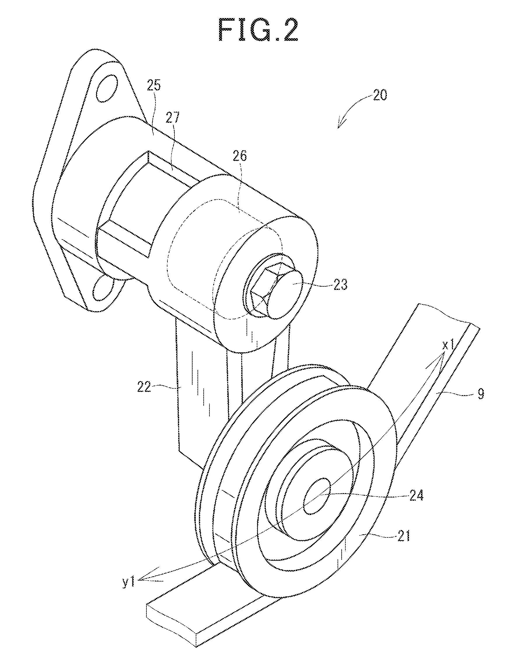
[0085]The first auto-tensioner 20 has the arms 22 whose end is borne by the shaft 12, so that the arm 22 is movable or swingable about the shaft 12 relative to the engine 2.

[0086]Similarly, the second auto-tensioner 30 has the arm 32 whose end is borne by the shaft 12, so that the arm 32 is movable or swingable about the shaft 12 relative to the engine 2.

[0087]The power transmission system 1 also includes a spring 28 which is connected at an end thereof to the shaft 24 of the first auto-tensioner 20 and at the other end to the shaft 34 of the second auto-tensioner 30. The spring 28 works as a biasing mechanism to urge the shafts 24 and 34 in a direction in which the shafts 24 and 34 approach each other. Specifically, the first tensioner pulley 21 and the second tensio...

third embodiment

[0091]FIG. 5 illustrates the power transmission system 1 according to the third embodiment which is different only in structure of the first auto-tensioner 20 from the first embodiment.

[0092]Specifically, the base 25 of the first auto-tensioner 20 is different in location of installation thereof from the first embodiment. Additionally, the first auto-tensioner 20 does not have the stopper 27.

[0093]In operation of the power transmissions system 1 of this embodiment, the ECU 70 actuates the given accessory 11 in the motor mode when the engine 2 is being stopped, so that the degree of tension of the belt 9 increases. This causes the arm 22 and the first tensioner pulley 21 to be swung in the direction y1 against the pressure, as produced by the spring 26, until it reaches the given position. When a direction in which force F, as exerted by the belt 9 on the first tensioner pulley 21 (i.e., the shaft 24), coincides with the length (i.e., the longitudinal center line) of the arm 22, the ...


PUM


Abstract

A power transmission system transmits power from an internal combustion engine to a first and a second auxiliary device through an endless transmitting member. Prior to issuing of an engine start request, the first auxiliary device is actuated to move a tensioner pulley to a given position to increase the degree of tension of the endless transmitting member. The actuation of the first auxiliary device as an engine starter upon the issuing of the engine start request, therefore, enables a drive shaft of the engine to be rotated immediately within a required time to crank the engine. This achieves a quick start of the engine and results in a decrease in amount of time between the issuing of the engine start request and the actual start of the engine.

Description

CROSS REFERENCE TO RELATED DOCUMENT[0001]The present application claims the benefit of priority of Japanese Patent Application No. 2013-259995 filed on Dec. 17, 2013 and Japanese Patent Application No. 2014-240982 filed on Nov. 28, 2014, disclosures of which are incorporated herein by reference.BACKGROUND OF THE INVENTION[0002]1. Technical Field[0003]This disclosure relates generally to a power transmission apparatus designed to transmit power, as produced by an internal combustion engine, to auxiliary devices.[0004]2. Background Art[0005]There are known power transmission systems which work to transmit output power of an internal combustion engine to a given accessory and other accessories mounted in, for example, an automobile using an endless transmitting member such as a belt. The given accessory is, for instance, an engine starter to start the internal combustion engine. The given accessory may be rotated by the output power of the internal combustion engine along with the othe...

Claims


Application Information

Patent Timeline
Patent Type & Authority Applications(United States)
IPC IPC(8): F16H7/12B60W10/08F02N15/02B60W20/00F02B67/06
CPCF16H7/1281B60W20/00F02B67/06Y10S903/909B60W10/08F16H2007/0812F16H2007/0885F02N15/02F02N11/04F02N11/0814F02N11/0844F02N15/08F02N2200/125Y02T10/40
Inventor NOGUCHI, HITOSHIOKADA, HIROSHINAKANO, TOMOAKIYAMASHITA, YOSHIHIROYAMAMOTO, YOUSUKEHARA, KAZUHISANAKAJIMA, TOSHIHISAMATSUO, KAZUKIMORI, TOSHIKAZUOE, SHUHEIKOKUMAI, HIKARUIWADE, KIYOSHI
Owner DENSO CORP
Why Eureka
Try Eureka