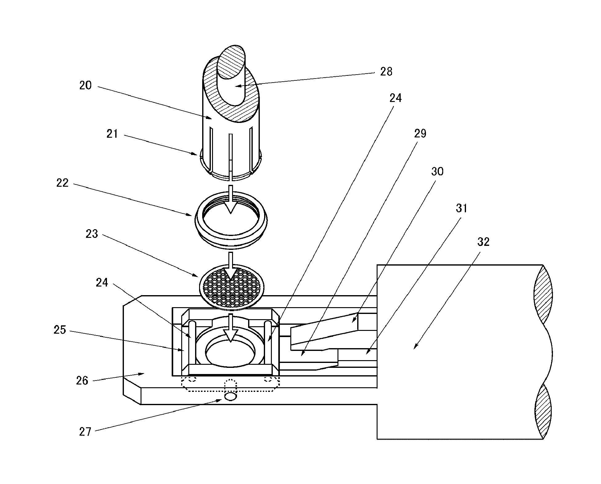
Specimen holder tip part, specimen holder having said specimen holder tip part, gonio stage, and electron microscope having said gonio stage
a technology of specimen holder and tip part, which is applied in the direction of optical radiation measurement, instruments, nuclear engineering, etc., can solve the problems of bending the specimen cradle part, minimize the damage of the specimen, and prevent accidental operation such as a spillage of liquid nitrogen
- Summary
- Abstract
- Description
- Claims
- Application Information
AI Technical Summary
Benefits of technology
Problems solved by technology
Method used
Image
Examples
example 1
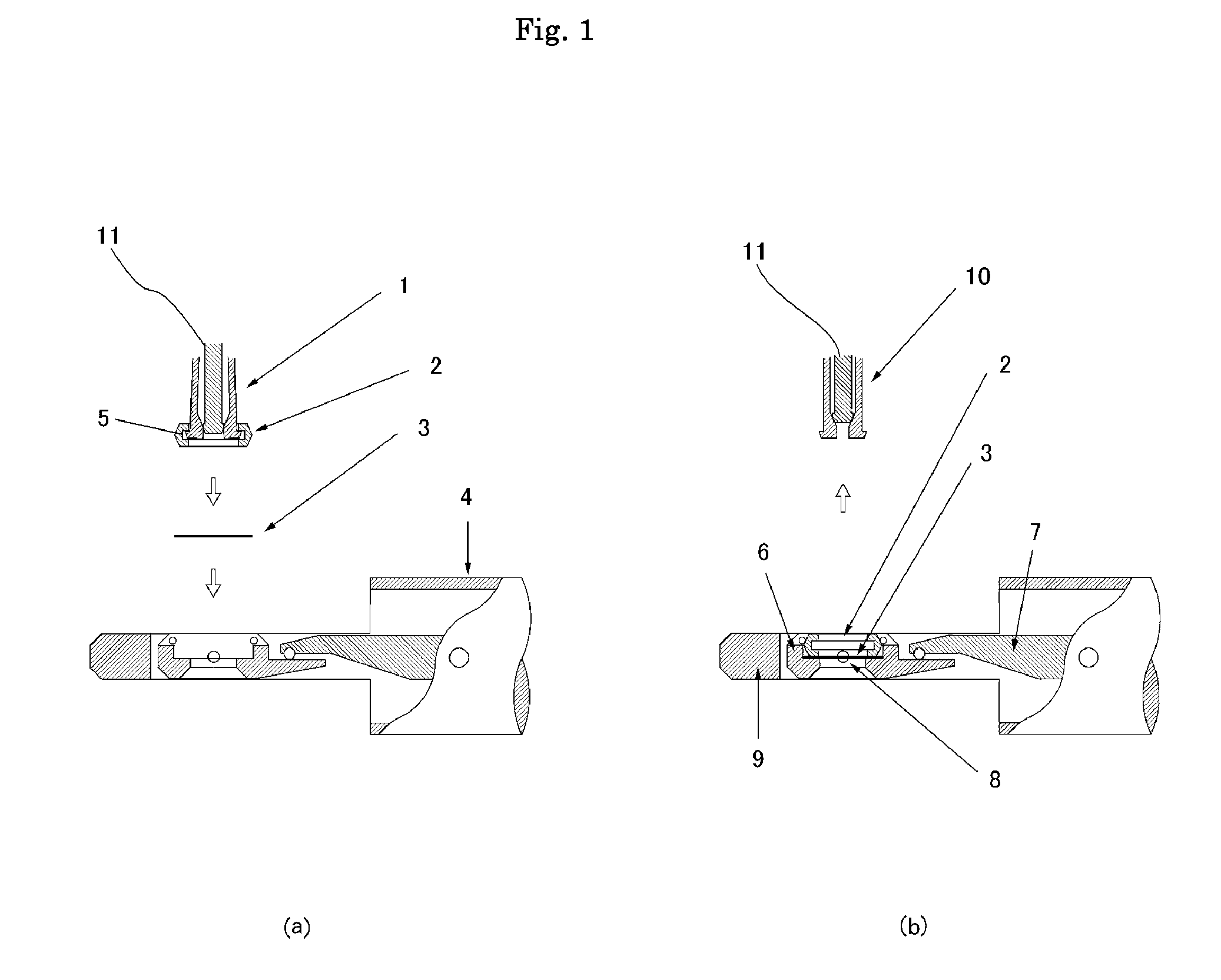
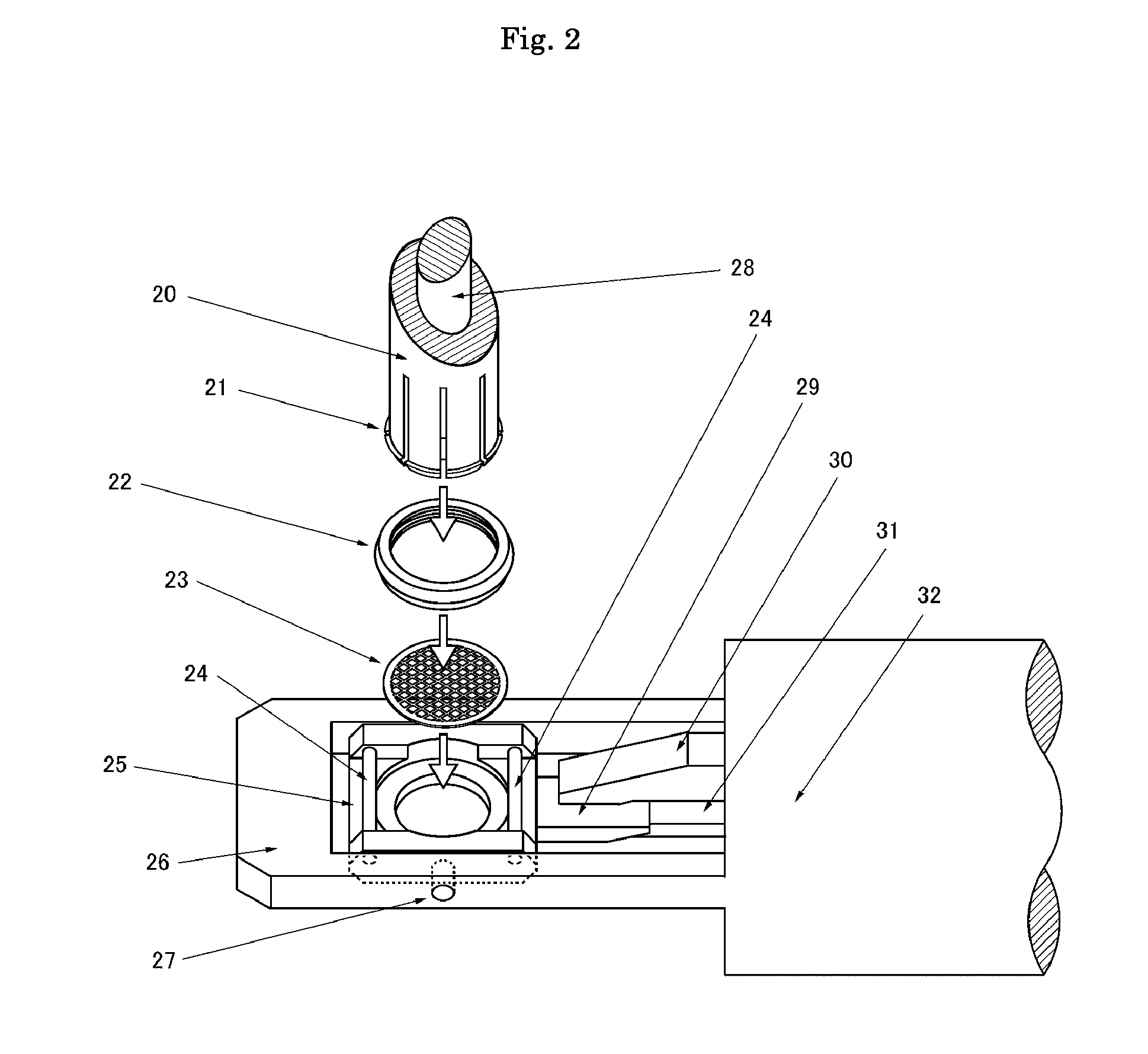
[0100]The following will be described an embodiment of the specimen holder tip of the present invention with reference to the drawings.
[0101]FIG. 1 is a sectional view showing a state of mounting the specimen in the case of using the specimen holder tip part of one embodiment of the present invention. FIG. 1 (b) shows a cross-sectional view of the specimen after mounting in the case of using the specimen holder tip part of one embodiment of the present invention. In FIG. 1, 1 is a removable tool, in this example, it is a jig for attaching the ring for holding the specimen. It shows a state of the collet retaining ring for holding the specimen. 2 is a specimen holding part, in this example, it is a ring for holding specimen. 3 is a specimen mesh, 4 is a specimen holder shaft portion, 5 is a desorption means for desorbing the specimen holding part (a groove in this case), 6 is a specimen setting seat (cradle body), 7 is a link to allow the cradle to tilt, 8 is a pivot pin supporting c...
example 2
[0108]The explanation of an embodiment of the specimen holder tip part of the present invention with reference to the drawings will be as follows.
[0109]FIG. 5 shows a diagram illustrating a procedure for mounting the specimen holder tip part of one embodiment of the present invention. In FIG. 5, 51 shows a schematic view from the state of being fixed by the fixing means to a state of loosening the fixing, 52 shows a schematic view from a state of loosening the fixing to a state of moving the means for holding specimen, 53 is a moving direction of the specimen holding means, 54 is a guide groove, 55 is a space for moving (groove), 56 is a grooves provided on the specimen setting seat, 57 is a fixing means, 58 is a specimen holder body, 59 is a specimen, 60 is a specimen holding means, 61 is an elastic member, 62 is a specimen setting seat (Cradle body), respectively.
[0110]In the prior art, the following steps 1 to 7 is required: 1. the step of loosening the specimen fixing means 57, ...
example 3
[0119]Then, the explanation of the present invention in a third aspect will be as follows. The electron microscope of the present invention is characterized in that it comprises a goniometer stage of the present invention described above in the third aspect. For electron microscopy, it is not particularly limited. Hereinafter, with reference to the drawings will be described an electron microscope and the goniometer stage of one embodiment of the present invention, but it is not intended that the present invention is not limited thereto.
[0120]FIG. 10 shows a conceptual view of the basic structure of one example of the applicable transmission electron microscope in the present invention. In FIG. 10, 101 is a vacuum area part, 102 is an electron acceleration electrode, 103 is an insulating gas area, 104 is a X-ray absorption member, 105 is a condenser aperture (movable mechanism part), 106 is an objective aperture (movable mechanism part), 107 is an aperture for limiting a visual fiel...
PUM
 Abstract
Description
Claims
Application Information
 - R&D
- Intellectual Property
- Life Sciences
- Materials
- Tech Scout
- Unparalleled Data Quality
- Higher Quality Content
- 60% Fewer Hallucinations
Browse by: Latest US Patents, China's latest patents, Technical Efficacy Thesaurus, Application Domain, Technology Topic, Popular Technical Reports.
© 2025 PatSnap. All rights reserved.Legal|Privacy policy|Modern Slavery Act Transparency Statement|Sitemap|About US| Contact US: help@patsnap.com


