

Transarterial heart assist device
- Summary
- Abstract
- Description
- Claims
- Application Information
AI Technical Summary
Benefits of technology
Problems solved by technology
Method used
Image

Examples
Embodiment Construction
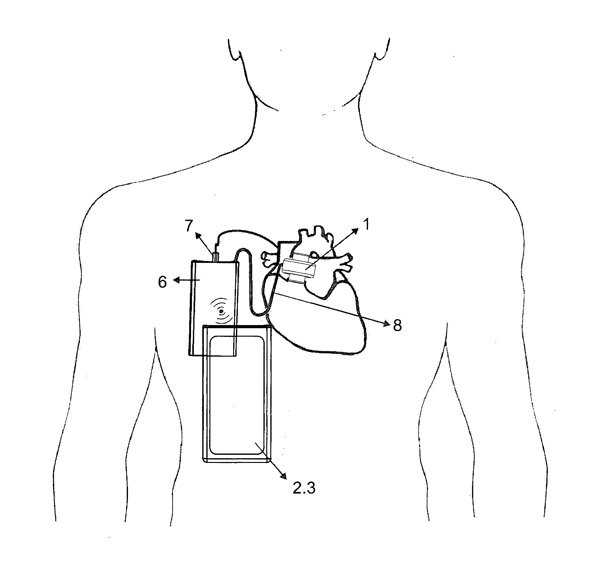
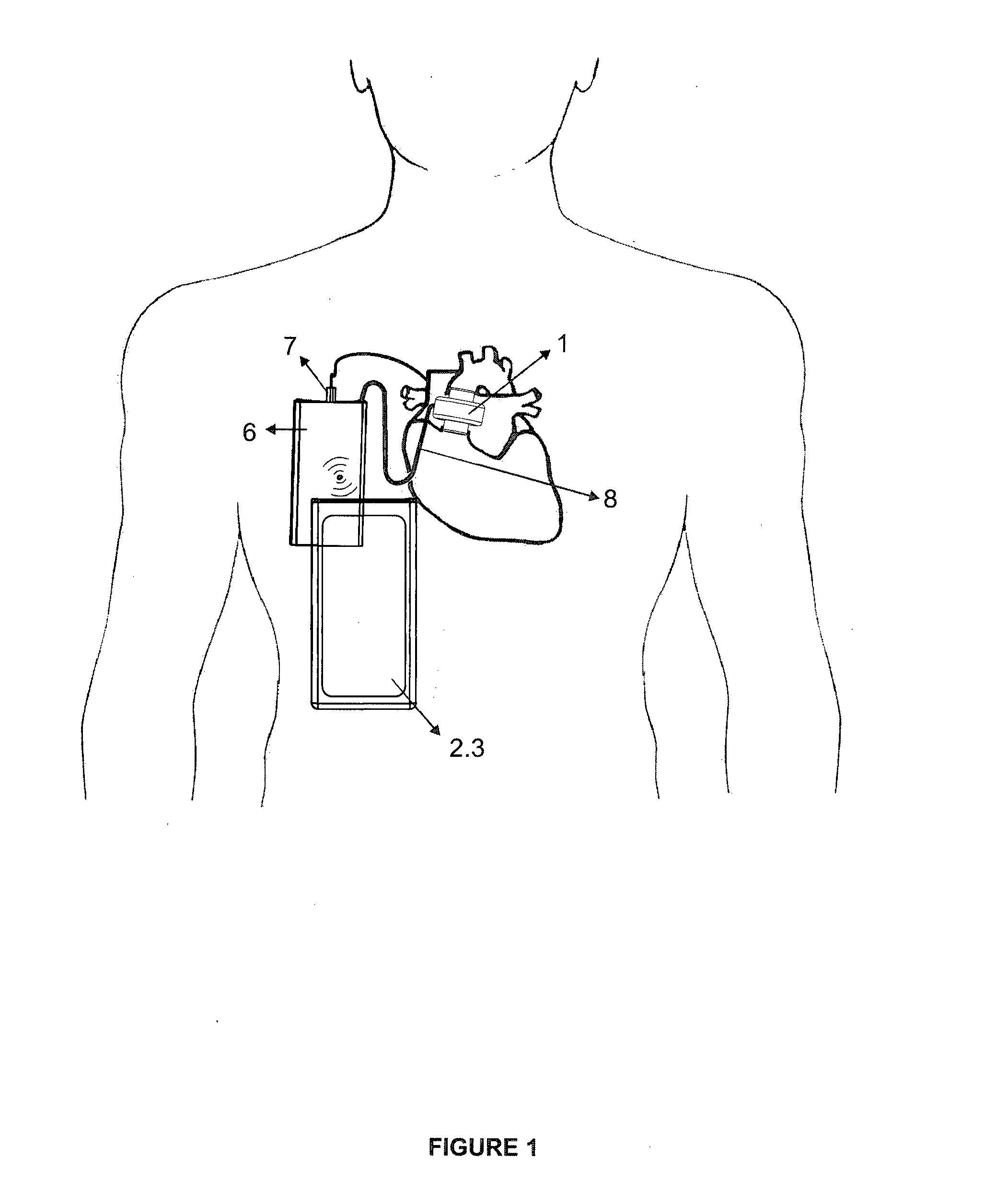
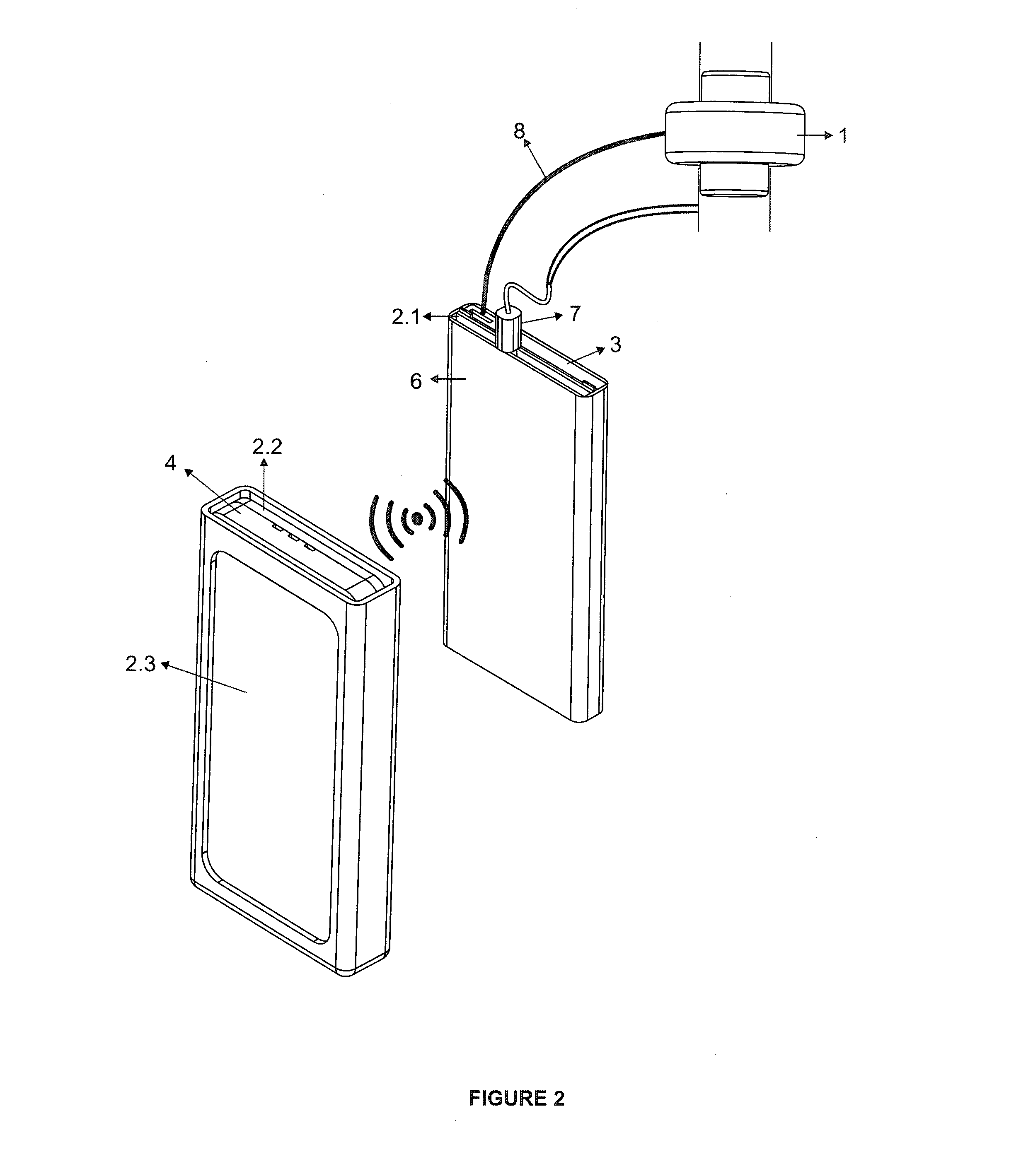
[0031]The heart support system comprises a motor (1), a control units (2), an internal control units (2.1), an external control units (2.2), an internal battery (3), an external battery (4), an energy transfers apparatus (5), a protective case (6), an ECG wires (7) and an electrical power cable (8). The motor (1); which has a rotor (1.1), a stator (1.2) and at least an airfoil (1.3). Generally composed of two cylindrical parts with the same axis, a stationary (stator) and revolving (rotor).
[0032]The heart support system has a rotor (1.1) and a stator (1.2). The stator (1.2) is located at the outer side, the cylindrical rotor which has natural magnet rods, aluminum or copper conductive bars located at the inner side.
[0033]The rotor (1.1) revolves in stator freely with the help of the magnetic field (bearing). Since there is no axis pin in the rotor (1.1) the helicoidal airfoils (1.3) are attached at the inner surface and an integrated cylindrical part is formed that rotates together ...
PUM
 Abstract
Description
Claims
Application Information