
Frequency-converted light source

Active Publication Date: 2015-06-25
SHARP KK
View PDF11 Cites 19 Cited by
  • Summary
  • Abstract
  • Description
  • Claims
  • Application Information

AI Technical Summary

Benefits of technology

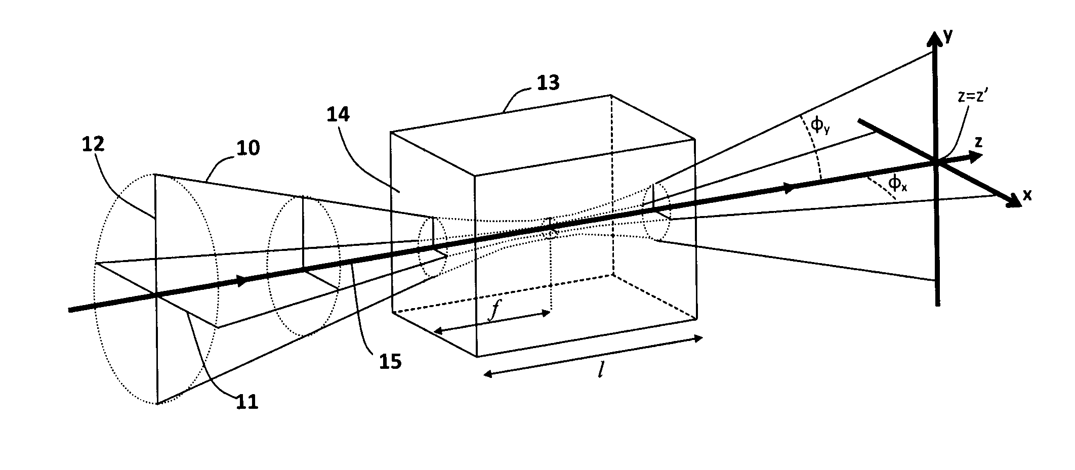
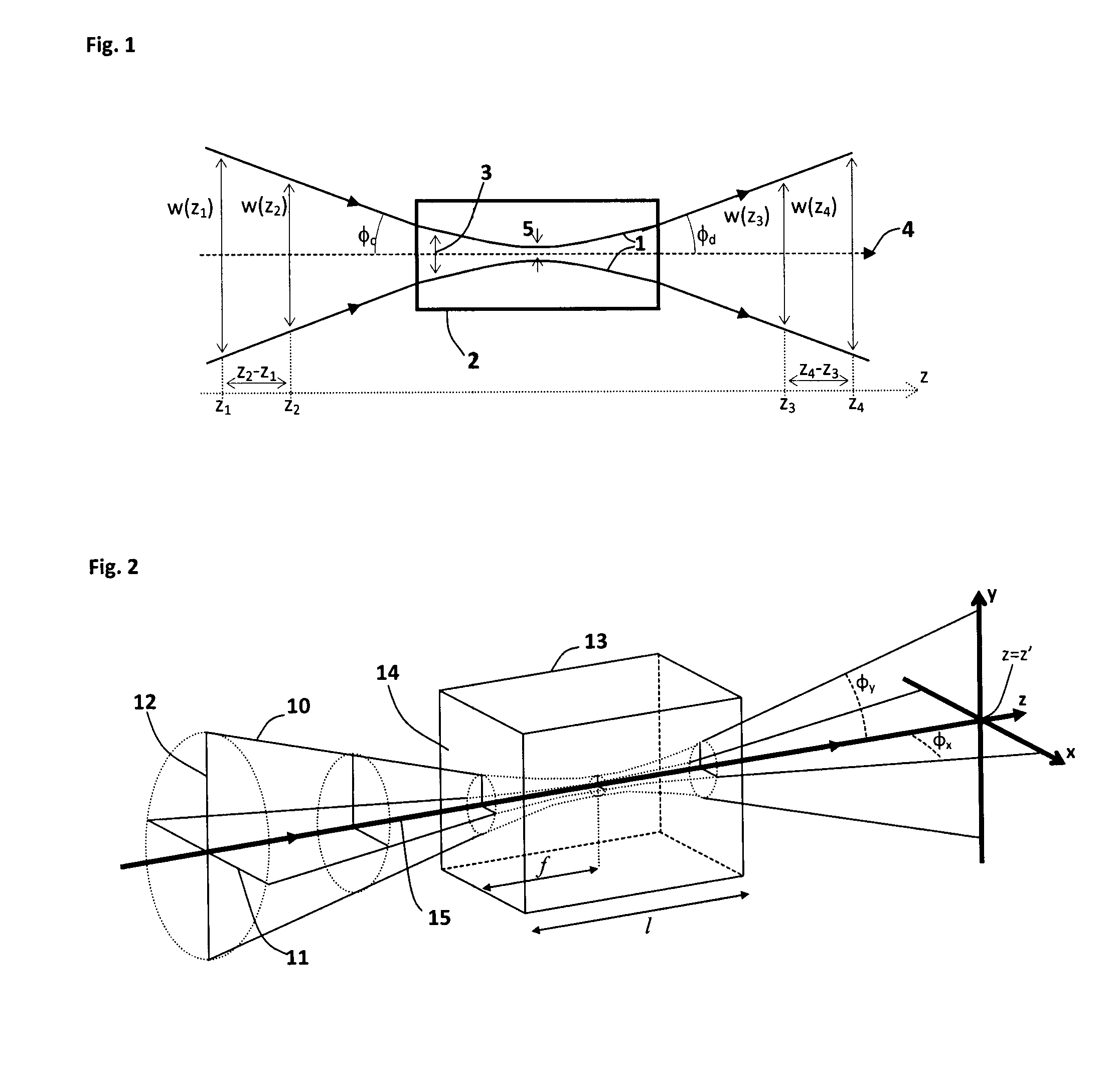
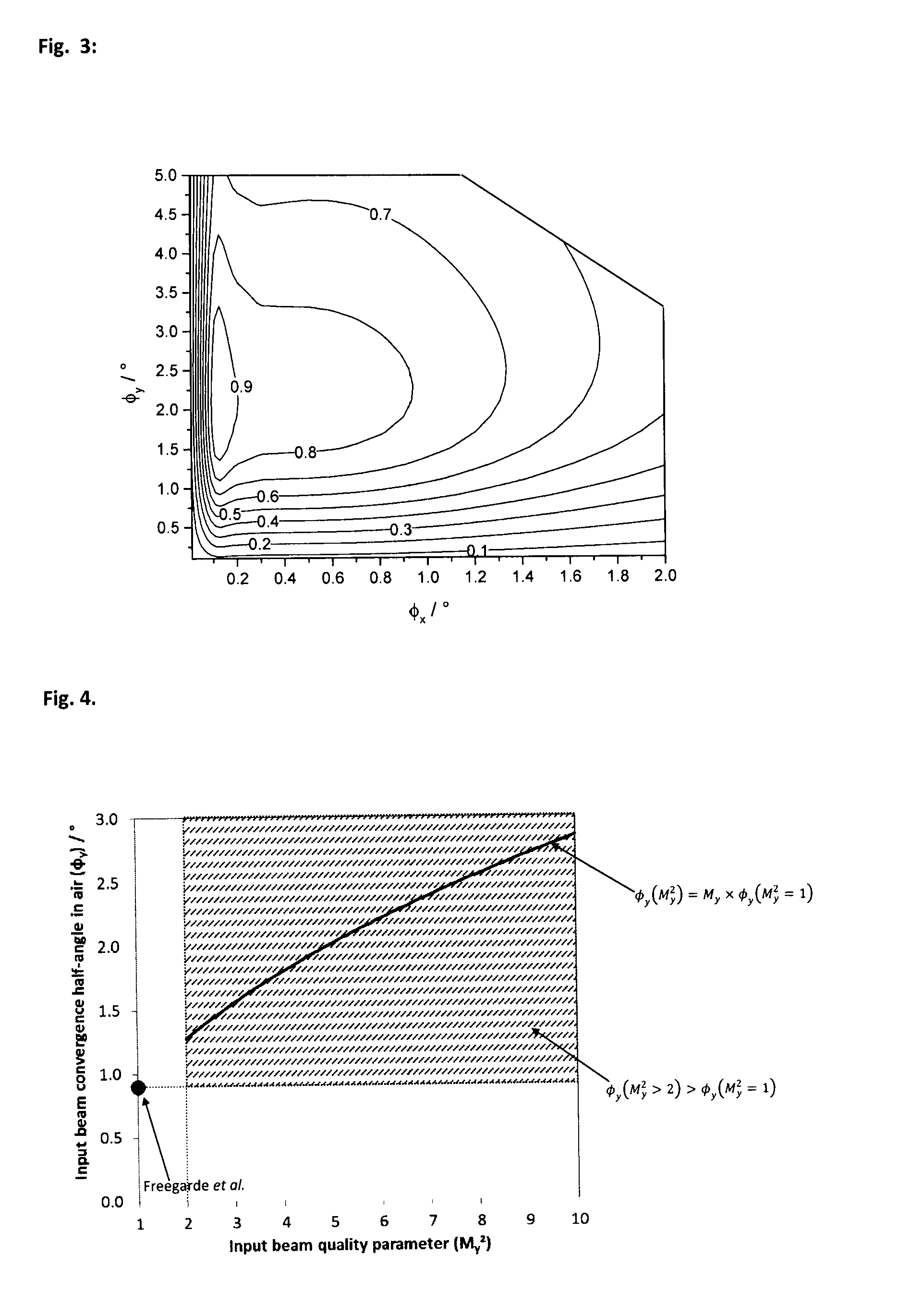
The present invention provides a new light source that uses laser diodes emitting non-diffraction-limited light to increase the power of the generated beam. This allows for the use of higher power laser diodes and increases the power of the generated beam. The light source includes a first light source with a convergence half-angle of φy≈2.11°, a second light source with a convergence half-angle of φy≈0.86°, and a third light source with a convergence half-angle of φy≈0.14°. The first light source has an output power of 235% of the second light source, and the third light source has an output power of very low accuracy. The new light source is significantly more powerful than previous light sources and can be used in applications such as non-linear optical frequency conversion.

Problems solved by technology

Furthermore, there are no methods described in the prior art which may be used to identify suitable strength of focussing of the input beam to obtain NLFC with high efficiency for non-diffraction-limited input beams in NLFC components which exhibit walkoff.

Method used


Image

  • Frequency-converted light source
  • Frequency-converted light source
  • Frequency-converted light source

Examples


example 1

[0117]A first example is a device for generation of ultraviolet light which has significant advantages over conventional devices in the prior art. The device includes a laser diode which emits non-diffraction-limited light, and this light undergoes SHG in an NLFC component resulting in a generated beam with wavelength shorter than 300 nm.

[0118]A schematic diagram of an exemplary laser device is shown in FIG. 6. The x-axis, y-axis and z-axis are defined in FIG. 6, and all references to these axes in the following description of this first example refer to this definition. The x-axis and z-axis are in the plane of the diagram in FIG. 6 and the y-axis is perpendicular to the plane of the diagram. A light source 20 includes a light emitting element such as a laser diode 21, an aspheric lens 22, a dichroic component 23, a first cylindrical lens 24, a second cylindrical lens 25, an NLFC component 26, a first filter 27, a spherical lens 28 and a second filter 29.

[0119]The laser diode emits...

example 2

[0148]A second example of this invention is now described. This second example is similar to the first example and common features will not be repeated. In this second example of the invention, the NLFC component 26 includes a β-BaB2O4 crystal which has a length, measured along the propagation direction of the input beam 33, of 15 mm. The orientation of the β-BaB2O4 crystal is the same as for the first example. The source beam 32 has the same properties as for the first example, for example a wavelength in air of approximately 445 nm and beam quality factors of Mx2=4.0 and My2=6.0 in the first and second planes of the beam respectively.

[0149]The suitable convergence half-angle in air of the input beam in the second plane of the beam (φy) to achieve high SHG efficiency is determined according to an aspect of the current invention; namely that φy(My2>2)>φy(My2=1). The suitable convergence half-angle in air for a diffraction-limited beam (My2=1) may be determined according to the metho...

example 3

[0152]A third example of the invention is now described. This third example is similar to the first example and common features will not be repeated. In this third example of the invention, the light emitted by the laser diode has a wavelength in air of approximately 416 nm. The beam quality factors of the source beam 32 are Mx2=5.0 and My2=8.0.

[0153]The NLFC component 26 includes a β-BaB2O4 crystal with the same orientation as for the first example, except that θ≈79.3° to provide Type 1 phase matching for a input beam with wavelength in air of 416 nm. For this example, when θ≈79.3°, the walkoff angle (ρ) of the generated beam is ρ≈2°.

[0154]The suitable convergence half-angle in air of the input beam in the second plane of the beam (φy) to achieve high SHG efficiency is determined according to an aspect of the current invention; namely that φy(My2>2)>φy(My2=1). The suitable convergence half-angle in air for a diffraction-limited beam (My2=1) may be determined according to the method...


PUM


Abstract

A nonlinear frequency conversion (NLFC) component is incorporated into a light source. The light source includes a light emitting element that emits a non-diffraction limited input light beam, and the NLFC component that exhibits walkoff and performs an NLFC process, such as second harmonic generation. An optical component is configured to converge the non-diffraction limited input beam into the NLFC component with a determined convergence half-angle. The convergence half-angle in air in a non-walkoff plane of the NLFC component is larger than a convergence half-angle angle for diffraction-limited light. Said convergence half-angle may be a multiple, ε×M, multiplied by the convergence half-angle value for diffraction-limited light, wherein ε has a value between a lower value equal to the larger of 0.4 and1Mand an upper value of 5.0, where M is the square root of the beam quality factor for the non-diffraction limited light.

Description

TECHNICAL FIELD[0001]The present invention relates to a light emitting device which includes a frequency-conversion process. The invention relates to the design of said device.BACKGROUND ART[0002]There are many examples in the prior art of photonic devices which exploit nonlinear optical properties of materials to convert input light with at least one frequency into generated light with at least one frequency different from the input frequency or frequencies. In one type of device, light of a first frequency (f1) passes through a material with a non-zero second order nonlinear susceptibility, and some or all of the input light is converted into generated light with a second frequency (f2), where f2=2f1. This process is commonly referred to as “second harmonic generation” (SHG) and sometimes as “frequency doubling”. In another type of device, input light including light with two different frequencies passes through a material with a non-zero second order nonlinear susceptibility, and...

Claims


Application Information

Patent Timeline
IPC IPC(8): G02F1/35F21K99/00G02F1/37
CPCG02F1/353F21Y2101/025F21K9/56G02F1/37F21K9/64F21Y2115/30F21Y2115/10G02F1/3503G02F1/3501G02F1/3551H01S5/0092H01S5/32341
Inventor SMEETON, TIM MICHAELBOARDMAN, EDWARD ANDREWWELNA, KARL PETER
Owner SHARP KK
Learn More