
Bearing structure and turbocharger

a bearing structure and turbocharger technology, applied in the direction of liquid fuel engines, machines/engines, mechanical apparatus, etc., can solve the problems of deteriorating affecting the dimensional precision of the clearance between the bearing and the drive shaft, and affecting the sliding performance of the drive shaft. , to achieve the effect of inhibiting the bearing surface of the bearing from rusting and maintaining the dimensional precision of the clearan

Active Publication Date: 2015-07-02
IHI CORP
View PDF7 Cites 4 Cited by
  • Summary
  • Abstract
  • Description
  • Claims
  • Application Information

AI Technical Summary

Benefits of technology

The present invention relates to a bearing structure and a turbocharger that can maintain the size and clearance between the shaft and bearing in their radial directions, while preventing the bearing surfaces from rusting. This is achieved by applying an anti-corrosion treatment to the outer peripheral surface of the drive shaft. The technical effect of this invention is to improve the performance of the drive shaft.

Problems solved by technology

As a result, water is highly likely to enter the clearance between the bearing and the drive shaft supported by the bearing.
Furthermore, combination of some engine use conditions increases likelihood that: rust is formed on the sliding surface of the drive shaft which slides in the bearing; and the sliding performance of the drive shaft accordingly deteriorates.
This is likely to worsen the sliding performance of the drive shaft.
Furthermore, it has been found from various experiments that so-called rust stains are one major cause of the rust formed on the sliding surface of the drive shaft.

Method used


Image

  • Bearing structure and turbocharger
  • Bearing structure and turbocharger
  • Bearing structure and turbocharger

Examples


Embodiment Construction

[0019]Referring to the accompanying drawings, detailed descriptions will be hereinbelow provided for a preferable embodiment of the present invention. Dimensions, materials, concrete values and the like will be given as examples in order to facilitate understanding of the invention, and do not limit the present invention unless otherwise stated. It should be noted that, in the specification and the drawings, components which have virtually the same functions and configurations will be denoted by the same reference signs, and thereby duplicated descriptions will be omitted from the specification. In addition, illustrations of components which have nothing direct to do with the present invention are omitted from the drawings.

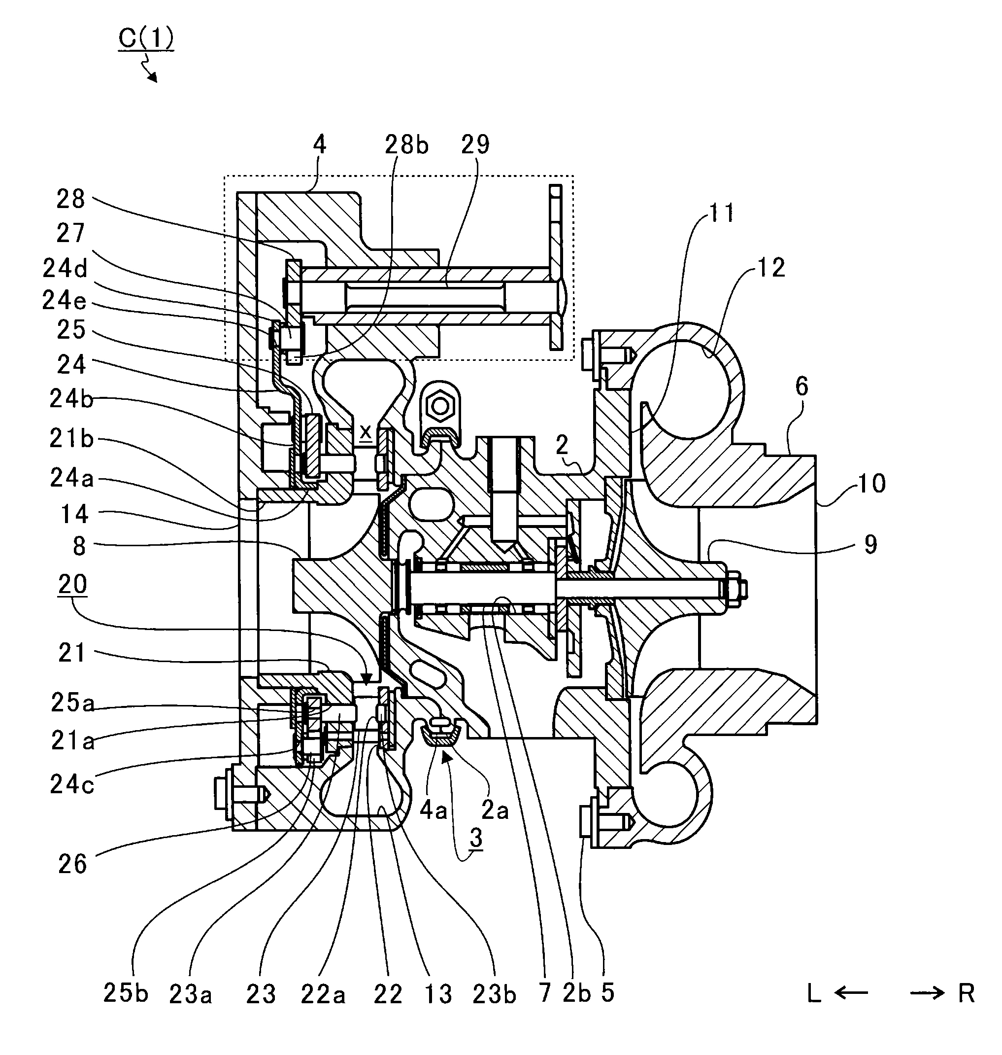
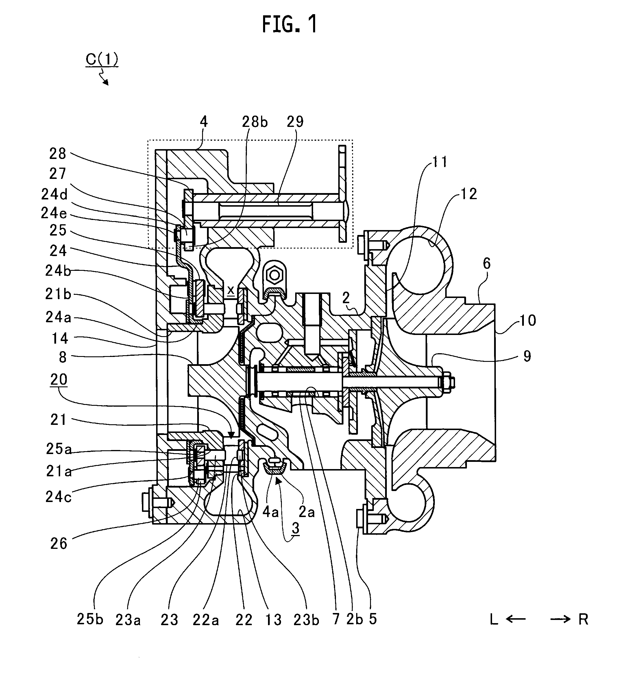
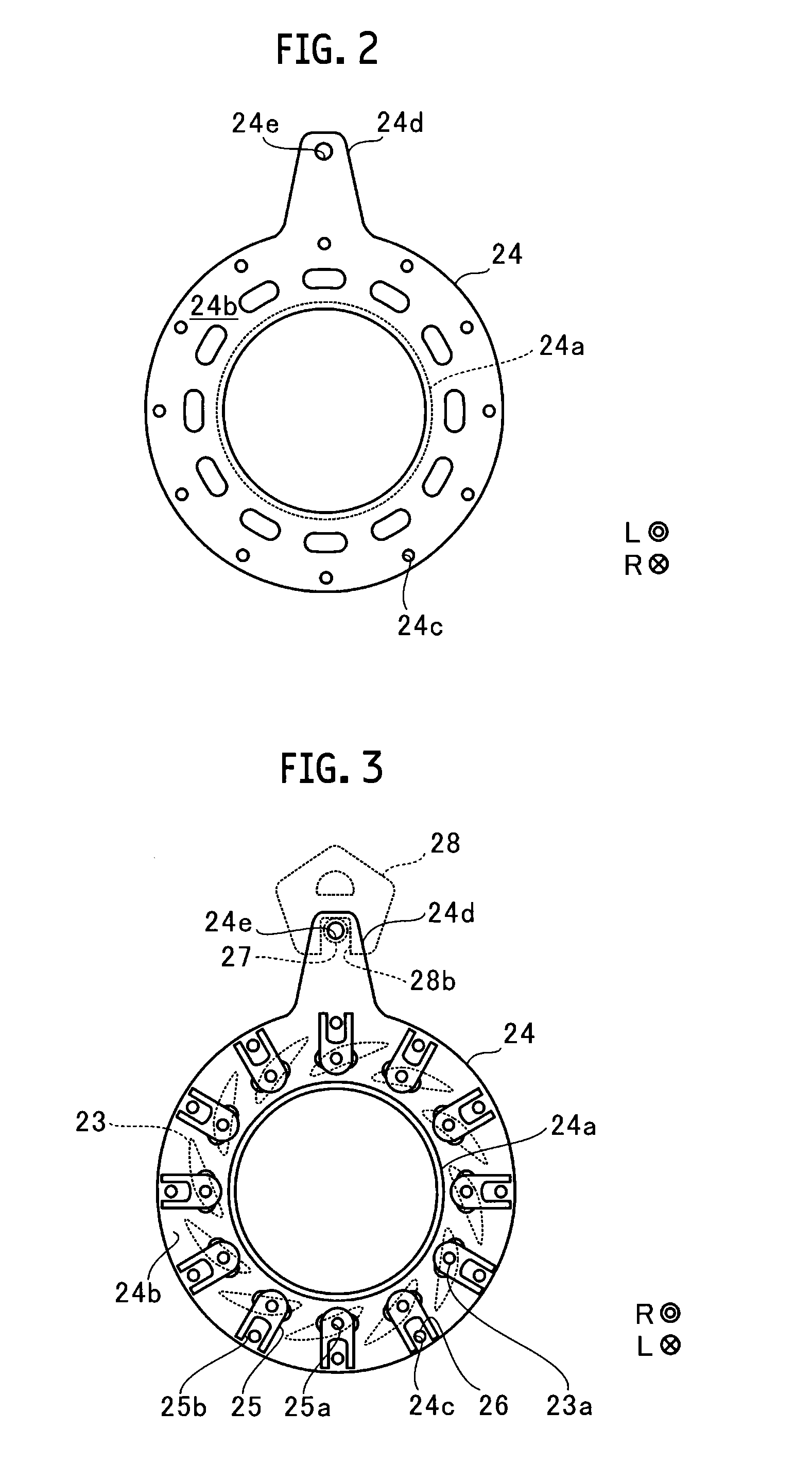
[0020]FIG. 1 is a schematic cross-sectional view of a turbocharger C. The following descriptions will be provided with arrow L and R directions in FIG. 1 pointing respectively to the left and right of the turbocharger C. As shown in FIG. 1, the turbocharger C incl...


PUM


Abstract

A shaft includes: two large-diameter portions; and a small-diameter portion formed between the two large-diameter portions. A bearing includes: an annular body in which to insert the shaft; two bearing surfaces being opposite the large-diameter portions; and an intervening surface located between the two bearing surfaces on an inner circumferential surface of the body, and being opposite the small-diameter portion with a clearance formed between the intervening surface and the small-diameter portion. No anti-corrosion treatment is applied to the large-diameter portions. An anti-corrosion treatment is applied to at least any one of: an exposed portion of an outer peripheral surface of the body of the bearing, which is exposed to the outside of the housing; the intervening surface of the bearing; an opposite end surface of the bearing; and the small-diameter portion of the shaft.

Description

CROSS REFERENCE TO RELATED APPLICATIONS[0001]This application claims priority to Japanese Patent Application No. 2013-273186 filed on Dec. 27, 2013, the entire contents of which are incorporated by reference herein.BACKGROUND OF THE INVENTION[0002]1. Field of the Invention[0003]The present invention relates to a bearing structure and a turbocharger each including a bearing which is attached to a housing of a turbocharger while penetrating the housing.[0004]2. Background of the Related Art[0005]Variable geometry system turbines have been used for turbochargers and the like. As disclosed in Japanese Patent Application Laid-Open Publication No. 2013-163972, in a variable geometry system turbine, multiple nozzle vanes are disposed annularly in alignment with each other in a passage through which to guide an exhaust gas to a turbine wheel from a scroll passage on the turbine side, and are fixed to their respective vane shafts. The vane shafts are rotatably supported by their respective s...

Claims


Application Information

Patent Timeline
IPC IPC(8): F01D25/16F16C33/12
CPCF01D25/166F05D2230/90F05D2220/40F16C33/121F01D17/165F16C2360/24
Inventor IIZUKA, KUNIAKIKITAZAWA, TOSHIHIKOEGUCHI, MASATOSHIASADA, YASUSHIKAGIMOTO, OSAMUISHIKAWA, KENJITAKAHASHI, MASASHIGESURUGA, YOHEIKATAYAMA, SUGURUYASUI, ASAKO
Owner IHI CORP
Learn More