LED with ceramic green phosphor and protected red phosphor layer

a technology of ceramic green phosphor and red phosphor, which is applied in the direction of semiconductor/solid-state device manufacturing, semiconductor devices, electrical devices, etc., can solve the problems of poor thermal transfer efficiency at this interface, inability to efficiently dissipate additional heat in the ceramic element, and inability to allow red conversion materials to be embedded in the ceramic element. to achieve the effect of thermal efficiency

Active Publication Date: 2015-07-02
LUMILEDS
View PDF5 Cites 11 Cited by
  • Summary
  • Abstract
  • Description
  • Claims
  • Application Information

AI Technical Summary

Benefits of technology

[0012]It would be advantageous to provide a thermal efficient light emitting device that produces a warmer color temperature than the conventional blue light emitting element with ceramic green converter element. It would also be advantageous to provide a method of producing such thermal efficient light emitting devices that provides for a consistent color temperature among the devices.

Problems solved by technology

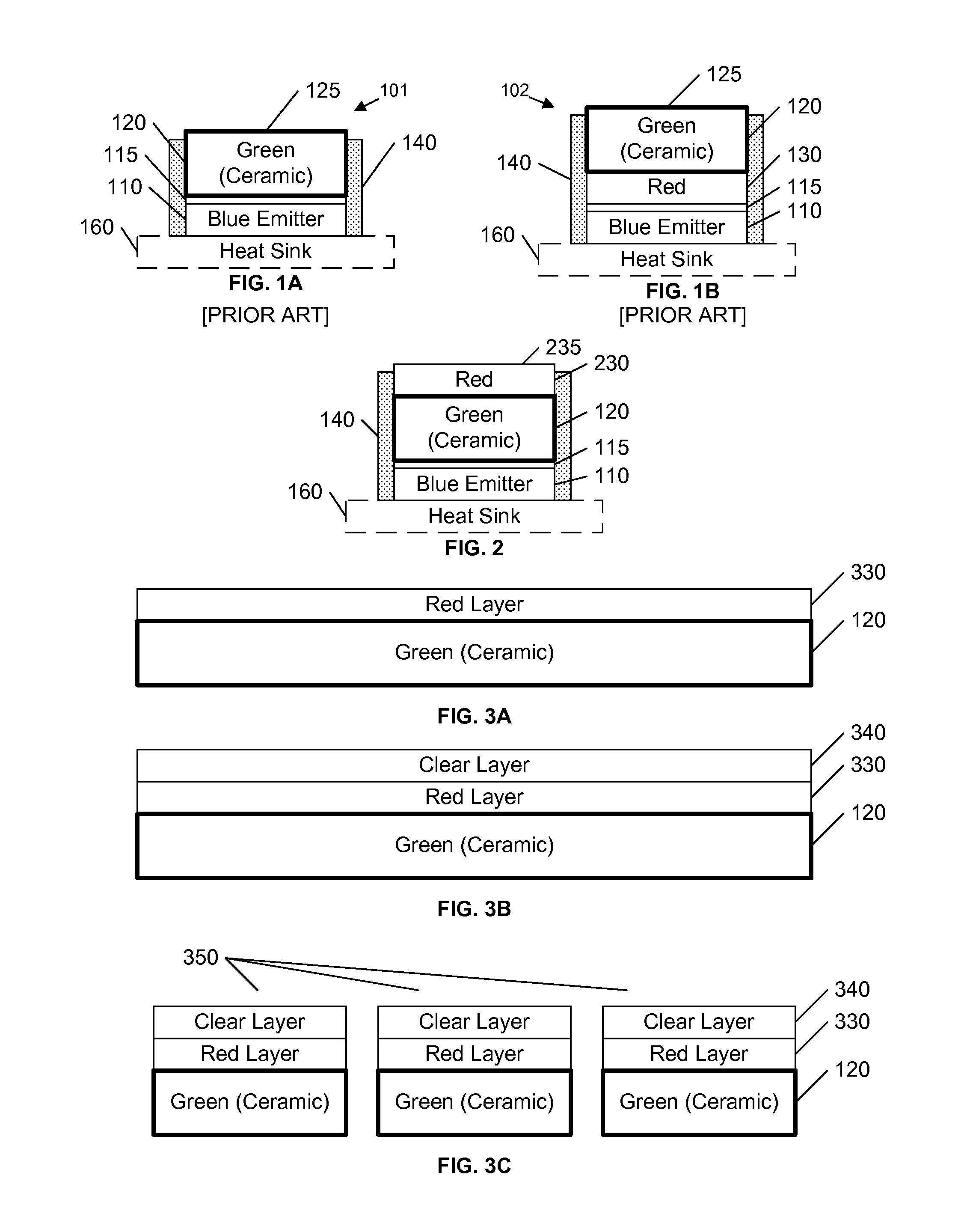
Current technology, however, does not allow for red conversion material to be embedded in a ceramic element, and therefore a separate coating, such as a red converter material loaded silicone layer 130, is applied between the (blue) light emitting element 110 and the ceramic (green) converter element 120.
As noted above, although the ceramic layer 120 may dissipate some heat through the upper surface 125 to the surrounding atmosphere, the thermal transfer efficiency at this interface is poor.
Although some of this heat will be transferred to the ceramic element 120, the ceramic element cannot efficiently dissipate this additional heat.
Thus, the expected operating temperature of the device of FIG. 1B will be high, increasing the likelihood of failure and reducing the device's life span.

Method used


Image

  • LED with ceramic green phosphor and protected red phosphor layer
  • LED with ceramic green phosphor and protected red phosphor layer
  • LED with ceramic green phosphor and protected red phosphor layer

Examples


Embodiment Construction

[0021]In the following description, for purposes of explanation rather than limitation, specific details are set forth such as the particular architecture, interfaces, techniques, etc., in order to provide a thorough understanding of the concepts of the invention. However, it will be apparent to those skilled in the art that the present invention may be practiced in other embodiments, which depart from these specific details. In like manner, the text of this description is directed to the example embodiments as illustrated in the Figures, and is not intended to limit the claimed invention beyond the limits expressly included in the claims. For purposes of simplicity and clarity, detailed descriptions of well-known devices, circuits, and methods are omitted so as not to obscure the description of the present invention with unnecessary detail.

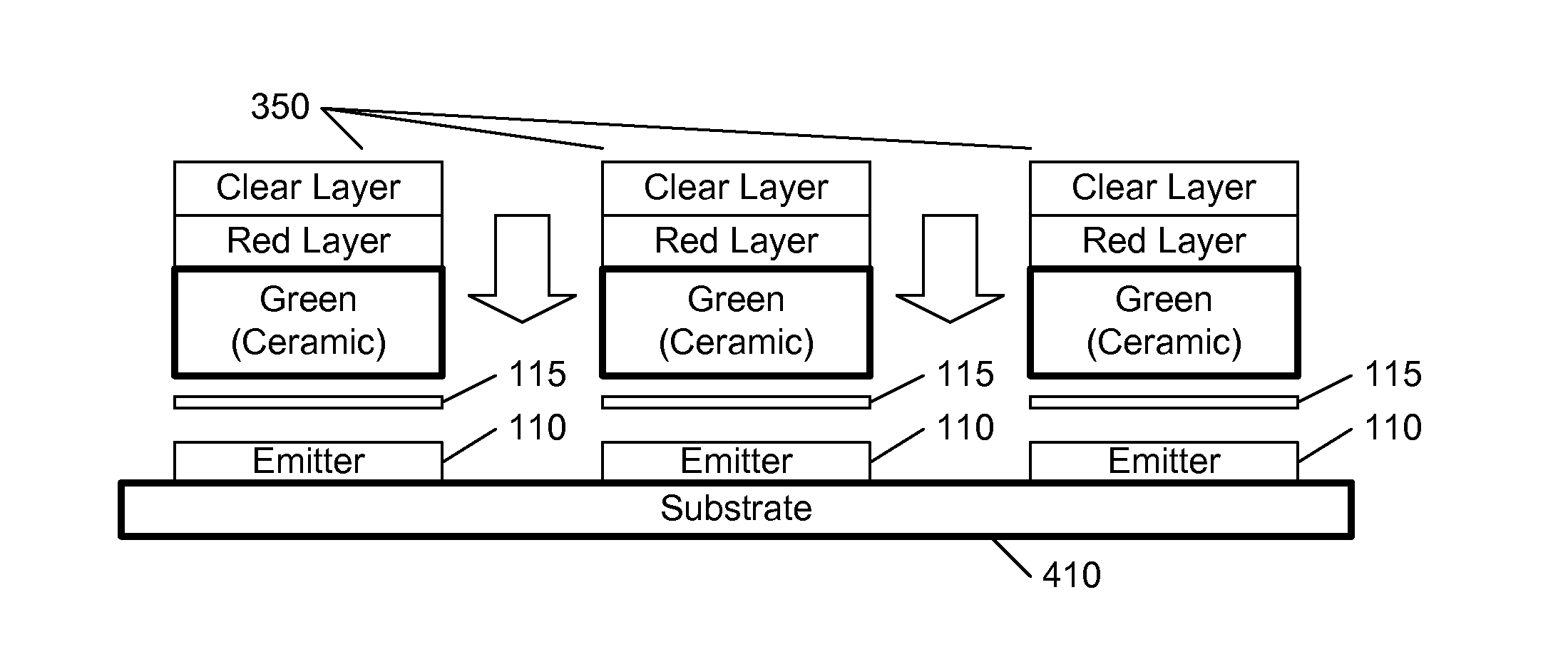
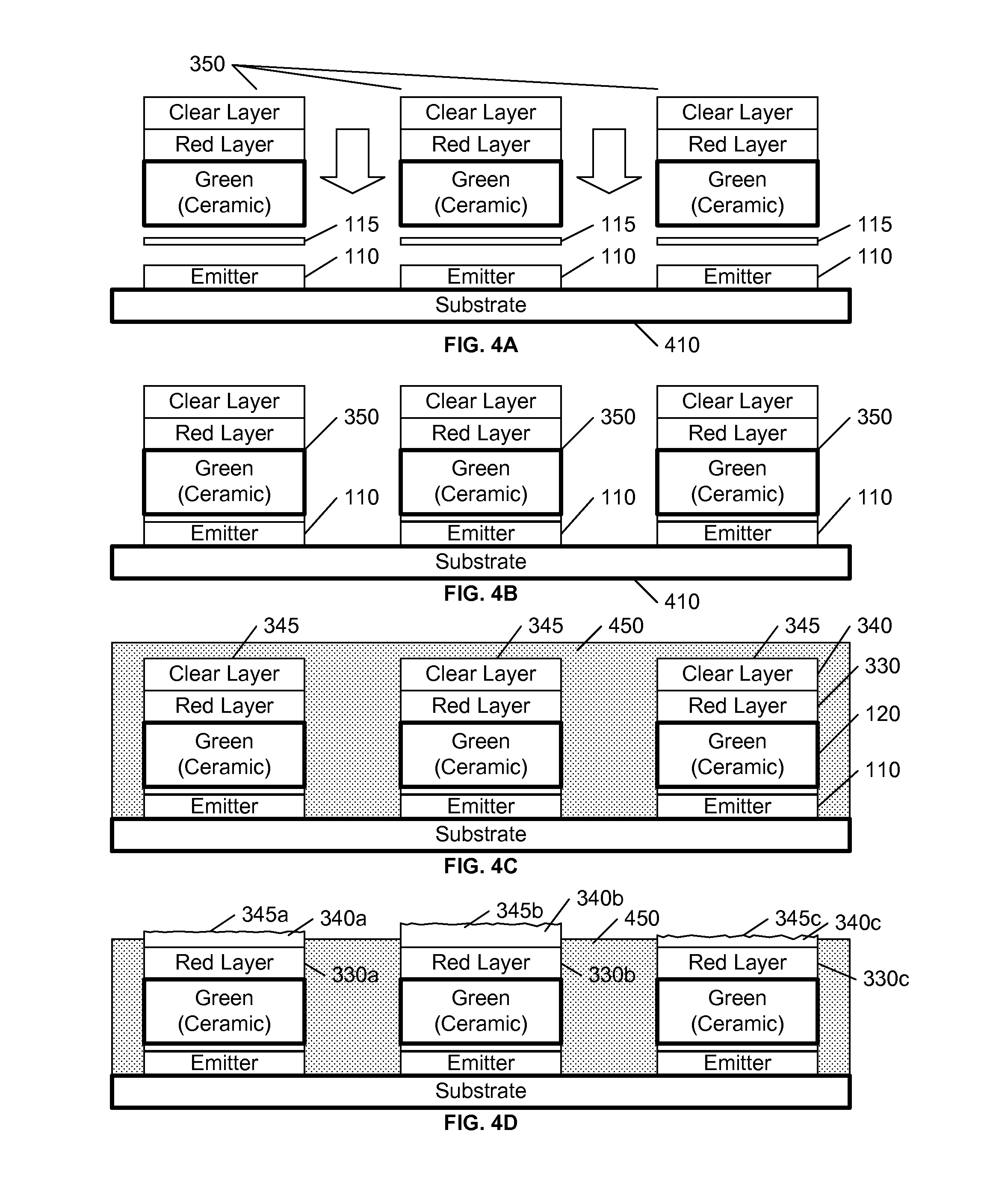
[0022]FIG. 2 illustrates an example light emitting device with a light emitting element 110, a ceramic green converter element 120, a protected ...


PUM

PropertyMeasurementUnit
thicknessaaaaaaaaaa
thicknessaaaaaaaaaa
diameteraaaaaaaaaa

Abstract

A ceramic green wavelength conversion element (120) is coated with a red wavelength conversion material (330) and placed above a blue light emitting element (110) such that the ceramic element (120) is attached to the light emitting element (110), thereby providing an efficient thermal coupling from the red and green converters (330, 120) to the light emitting element (110) and its associated heat sink. To protect the red converter coating (330) from the effects of subsequent processes, a sacrificial clear coating (340) is created above the red converter element (330). This clear coating (340) may be provided as a discrete layer of clear material, or it may be produced by allowing the red converters to settle to the bottom of its suspension material, thereby forming a converter-free upper layer that can be subjected to the subsequent fabrication processes.

Description

FIELD OF THE INVENTION[0001]This invention relates to the field of light emitting devices, and in particular to a light emitting device that includes a light emitting element, a ceramic green-wavelength conversion element, and a red-wavelength conversion layer.BACKGROUND OF THE INVENTION[0002]Wavelength converters, such as phosphors, are commonly used to provide light comprising a plurality of wavelengths from a single wavelength light emitting element. The composite light output is commonly a combination of the light emitted from the converters upon absorption of some of the light emitting from the light emitting element, and the remainder of the non-absorbed light from the light emitting element.[0003]In an example embodiment such as illustrated in FIG. 1A, the light emitting device 101 includes a light emitting element 110 that emits blue light and a ceramic element 120 above it that includes blue-to-green wavelength converter material. For ease of reference, a wavelength convert...

Claims


Application Information

Patent Timeline
Patent Type & Authority Applications(United States)
IPC IPC(8): H01L33/50
CPCH01L2933/0041H01L33/504H01L33/0041H01L33/508H01L2924/12041H01L33/60H01L33/642H01L2933/0058
Inventor SCHRICKER, APRIL DAWNMAI, KIM KEVINBASIN, GRIGORIYMACKENS, UWEVOGELS, JOOST PETER ANDREWEIJERS, ALDEGONDA LUCIAZIJTVELD, KARL ADRIAAN
Owner LUMILEDS
Why Eureka
Try Eureka