
Powder supply device

a technology of supply device and powder supply, which is applied in the direction of bulk conveyor, transportation and packaging, manufacturing tools, etc., can solve the problems of powder supply quantity variation, and achieve the effect of simple configuration, stab supply, and greatly increased quality and productivity of the product subjected to laser cladding processing

Active Publication Date: 2015-07-09
TOYOTA JIDOSHA KK
View PDF8 Cites 10 Cited by
  • Summary
  • Abstract
  • Description
  • Claims
  • Application Information

AI Technical Summary

Benefits of technology

The powder supply device in this patent allows for the stable supply of powder from one hopper to another without the need for component replacement. This is achieved by guiding the powder downward from the first hopper and pressure-fed it to the second hopper using a carrier gas. This simple configuration ensures a reliable and precise supply of powder for laser cladding processing, improving the quality and productivity of the final product.

Problems solved by technology

Thus, there may be caused the problem of variations in the amount of supply of powder due to changes in performance of the replenish valve over time caused by, the seizure of the powder on the replenish valve.

Method used


Image

  • Powder supply device
  • Powder supply device
  • Powder supply device

Examples


first embodiment

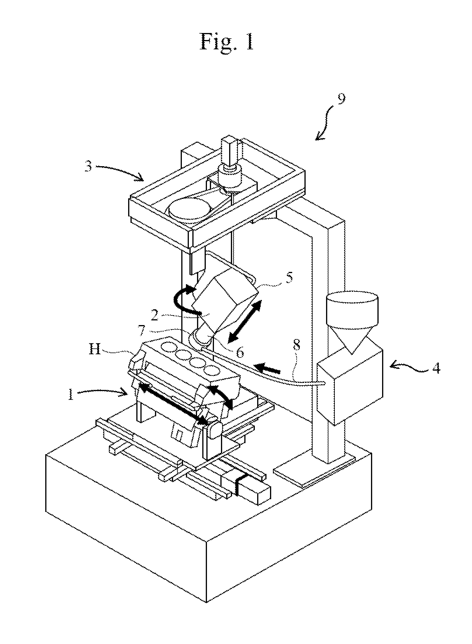
[0027]FIG. 1 is a perspective view schematically illustrating main elements of a laser cladding processing device 9 to which a first embodiment of the powder supply device according, to the present invention is applied.

[0028]The laser cladding processing device 9 is a device for performing laser cladding processing on a valve seat portion of a cylinder head H, for example, and includes a cylinder head holder device 1 for tilting and holding the cylinder head H; a laser processing head 2 that discharges powder metal (powder) (such as a material including copper as a principal component) while irradiating a processing location with laser light; a rotation device 3 that rotates the laser processing head 2 around a vertical axis while holding the laser processing head 2 at an angle with respect to the vertical direction; and a powder supply device 4 that supplies the powder metal to the laser processing head 2.

[0029]The cylinder head holder device 1 tilts the cylinder head H so as to al...

second embodiment

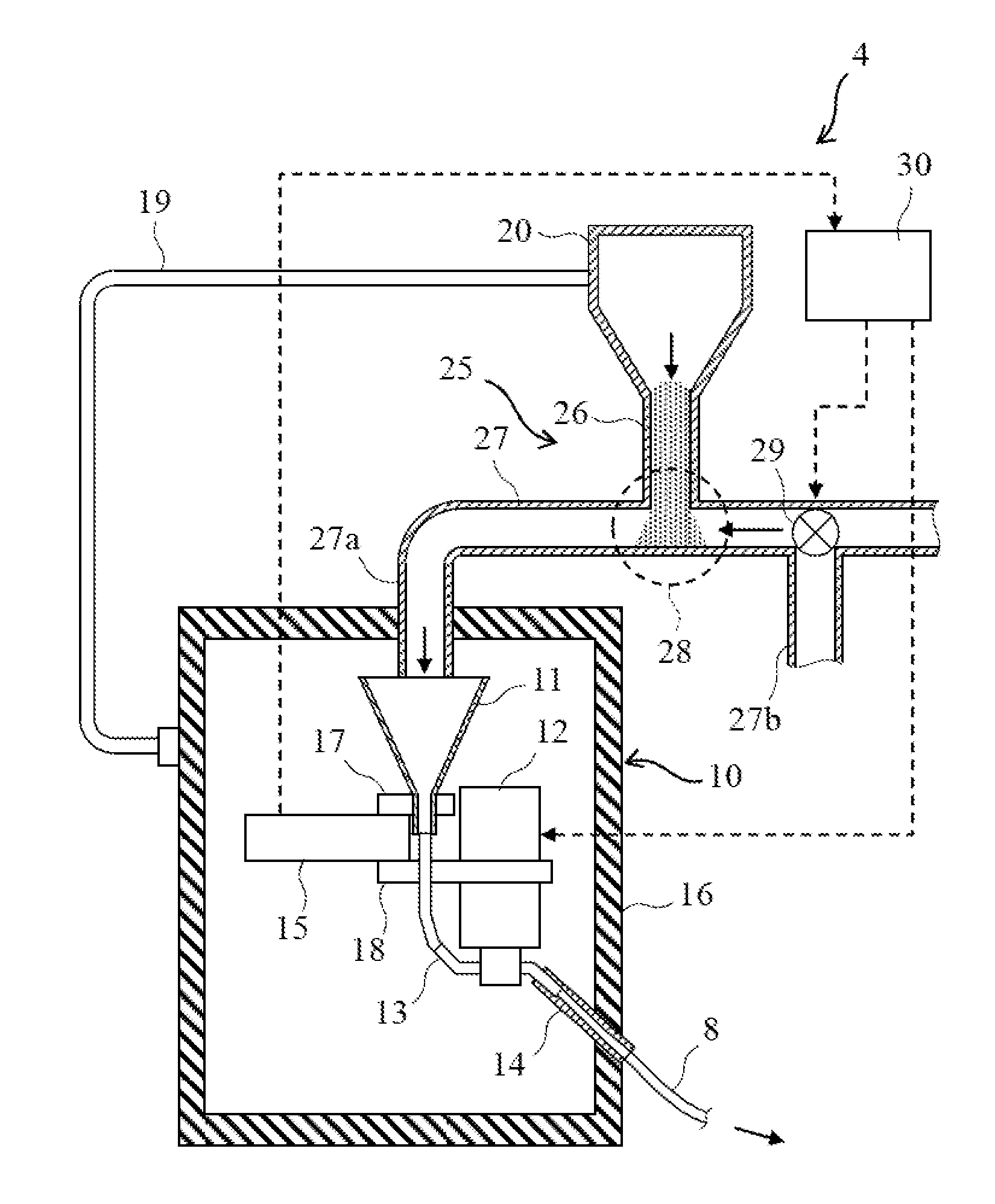
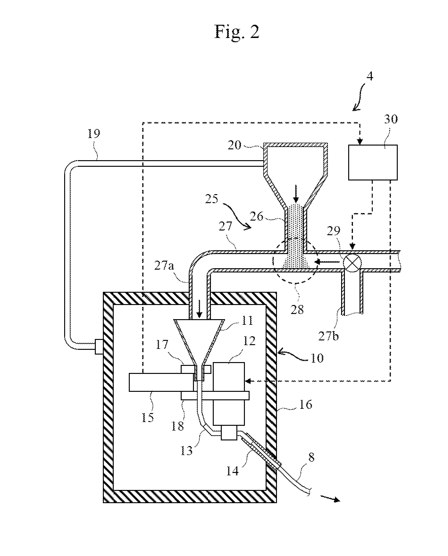
[0042]FIG. 3 is an overall configuration diagram illustrating the overall configuration of the powder supply device according to a second embodiment of the present invention. The powder supply device according to the second embodiment illustrated in FIG. 3 differs from the powder supply device of the first embodiment illustrated in FIG. 2 mainly in the configuration of the intersecting portion of the first piping and the second piping, and is similar to the powder supply device of the first embodiment in other elements. Thus, the elements similar to those of the first embodiment will be designated with similar signs and their detailed description will be omitted.

[0043]In a powder supply device 4A illustrated in FIG. 3, a second piping 27A includes a curved portion 27cA protruding downward at an intersecting portion 28A of a first piping 26A and the second piping 27A.

[0044]Because of the curved portion 27cA protruding downward at the intersecting portion 28A as described above, the p...


PUM


Abstract

Provided is a powder supply device that can stably supply powder from a main hopper to a powder supply means including a sub-hopper without requiring component replacement and the like. The powder supply device is provided with: a first piping that guides powder accumulated in a main hopper downward; a second piping that is connected to the first piping at a lower end portion thereof while intersecting with the first piping, and that guides the powder guided by the first piping to a sub-hopper; and a switching valve that pressure-feeds the powder temporarily deposited while forming an angle of repose at an intersecting portion of the first piping and the second piping, to the sub-hopper.

Description

BACKGROUND[0001]1. Technical Field[0002]The present invention relates to powder supply devices, and particularly to a powder supply device for supplying a powder, such as powder metal and the like, used for laser cladding processing, for example.[0003]2. Background Art[0004]Conventionally, laser processing is known whereby, e.g., in order to increase the durability of the valve seat of an engine cylinder head while increasing its design freedom, the valve seat is irradiated with laser while a powder (powdered) overlay material, for example, is supplied, forming an overlay layer (cladding layer) as the valve seat and the laser are relatively rotated. This laser processing is a technology where the cylinder head that has been subjected to machining processing required for an engine combustion chamber, such as valve opening forming processing, is irradiated with laser while the powdered overlay material including a copper alloy and the like and having abrasion resistance is supplied to...

Claims


Application Information

Patent Timeline
IPC IPC(8): B65G53/04B65G53/52B65G65/40
CPCB65G53/04B65G53/52B65G65/40B23K26/00B23K26/144B65G53/10
Inventor SATO, AKIOKIDERA, KENJIKUME, NORIKAZU
Owner TOYOTA JIDOSHA KK
Learn More