
Reducing agent tank and work vehicle

Active Publication Date: 2015-07-09
KOMATSU LTD
View PDF14 Cites 8 Cited by
  • Summary
  • Abstract
  • Description
  • Claims
  • Application Information

AI Technical Summary

Benefits of technology

The present invention improves how heat is transferred to a reducing agent, making it more effective. It also reduces uneven heat transfer in the tank where the reducing agent is stored.

Problems solved by technology

When the reducing agent is frozen in the tank, the reducing agent cannot be supplied to the exhaust gas treatment device.

Method used


Image

  • Reducing agent tank and work vehicle
  • Reducing agent tank and work vehicle
  • Reducing agent tank and work vehicle

Examples


Embodiment Construction

[0034]Hereinafter, an embodiment will be described with reference to the drawings.

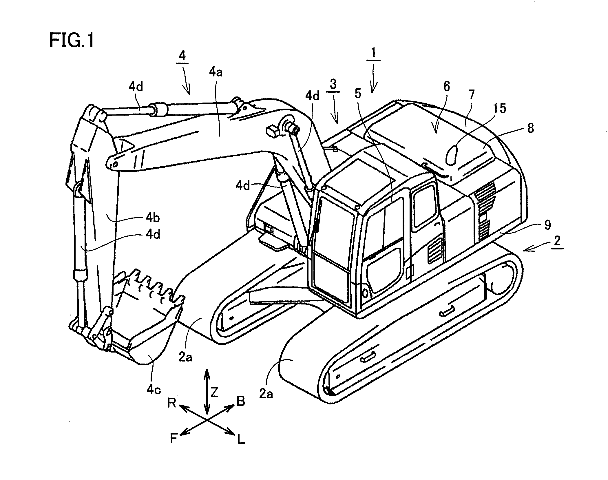
[0035]Firstly, a configuration of a hydraulic excavator will be described with reference to FIG. 1, as one example of work vehicles to which an idea of the present invention is applicable. It should be noted that the present invention is applicable to work vehicles such as a wheel loader, a bulldozer, and the like provided with an engine unit including an exhaust gas treatment unit.

[0036]FIG. 1 is a perspective view schematically representing a configuration of a hydraulic excavator 1 as a work vehicle according to one embodiment of the present invention. Referring to FIG. 1, hydraulic excavator 1 mainly includes an undercarriage 2, an upper revolving unit 3, and a work implement 4. Undercarriage 2 and upper revolving unit 3 constitute a work vehicle main body.

[0037]Undercarriage 2 includes a pair of left and right crawler belts 2a. Undercarriage 2 is configured to be self-propelled by rotation of the ...


PUM


Abstract

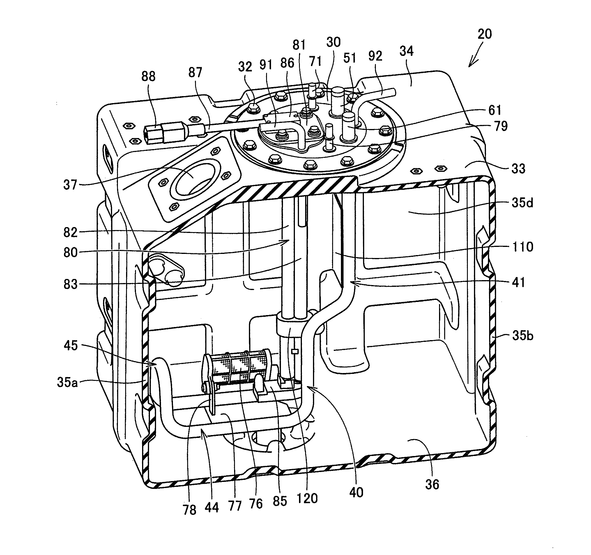
A reducing agent tank is provided which can improve a heat transfer efficiency to a reducing agent and transfer heat to the reducing agent in a height direction of the reducing agent tank without unevenness. The reducing agent tank includes a container main body which has an upper face and a bottom face and constitutes a space for storing the reducing agent between the upper face and the bottom face, and a heat exchanger which performs heat exchange with the reducing agent. The heat exchanger has penetrating portions and inclined portions. The penetrating portions penetrate to the upper face of the container main body and extend into the space. The inclined portions are inclined relative to the penetrating portions at a position different from each other in an extending direction of the penetrating portions and extend toward a side of the bottom face.

Description

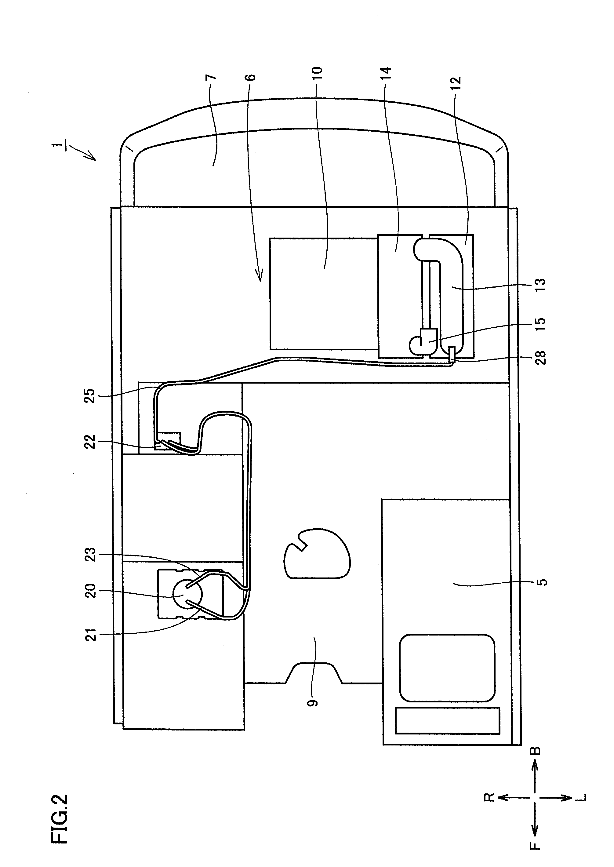
TECHNICAL FIELD[0001]The present invention relates to a reducing agent tank and a work vehicle.BACKGROUND ART[0002]Work vehicles such as a hydraulic excavator, a bulldozer, a wheel loader, and the like have an exhaust gas treatment device. For example, a diesel particulate filter device (DPF), a diesel oxidation catalyst device (DOC), a selective catalytic reduction device (SCR), and the like are available as exhaust gas treatment devices. Particularly, the selective catalytic reduction device reduces nitrogen oxide contained in an exhaust gas to purify the exhaust gas. A reducing agent used for this exhaust gas treatment is stored in a reducing agent tank.[0003]When the reducing agent is frozen in the tank, the reducing agent cannot be supplied to the exhaust gas treatment device. Therefore, for the purpose of preventing freezing of the reducing agent in the reducing agent tank, the technique of arranging a heat exchanger in the reducing agent tank to heat the reducing agent has be...

Claims


Application Information

Patent Timeline
IPC IPC(8): F01N3/28F01N3/20
CPCF01N3/208F01N3/2896F01N3/2066F01N2610/02F01N2610/10F01N2610/1406F01N2590/08Y02A50/20Y02T10/12
Inventor OGAWA, SATOSHIKUSABA, TAISUKEKUSE, YASUTAKA
Owner KOMATSU LTD
Learn More