
Ultra-rapid and sensitive DNA detection using dnazyme and on-chip isotachophoresis

a dna detection and sensitive technology, applied in the field of dna detection, can solve the problems of low robustness, low specificity of detection, time-consuming, complex (low robustness) and expensive, etc., and achieve the effect of rapid and inexpensive dna detection techniques

Inactive Publication Date: 2015-07-16
KONICA MINOLTA LAB U S A INC
View PDF2 Cites 4 Cited by
  • Summary
  • Abstract
  • Description
  • Claims
  • Application Information

AI Technical Summary

Benefits of technology

This patent describes a method for detecting DNA using a special technology that combines two techniques: isotachophoresis and DNAzyme. This technology allows for fast and highly-sensitive detection of DNA. The method involves using a microfluidic chip with two reservoirs and a fluid channel between them. A sample containing DNA and a special DNAzyme sensor is mixed and then an electric charge is applied between the two reservoirs. The sensor is designed to specifically detect the presence of the target DNA sequence and can generate a fluorescent signal. The method can be used in various applications such as genetic testing and disease diagnosis. Overall, this patent presents a reliable and efficient way to detect DNA in a fast and accurate way.

Problems solved by technology

However, they are time-consuming, complex (low robustness) and expensive.
The above-described on-chip ITP technique achieves ultra-rapid reaction, but it only achieves moderate sensitivity and the specificity of detection is low.
The DNAzyme technique can provide signal amplification (i.e. high sensitivity) and high specificity, but the reaction speed is slow.

Method used


Image

  • Ultra-rapid and sensitive DNA detection using dnazyme and on-chip isotachophoresis
  • Ultra-rapid and sensitive DNA detection using dnazyme and on-chip isotachophoresis
  • Ultra-rapid and sensitive DNA detection using dnazyme and on-chip isotachophoresis

Examples


first embodiment

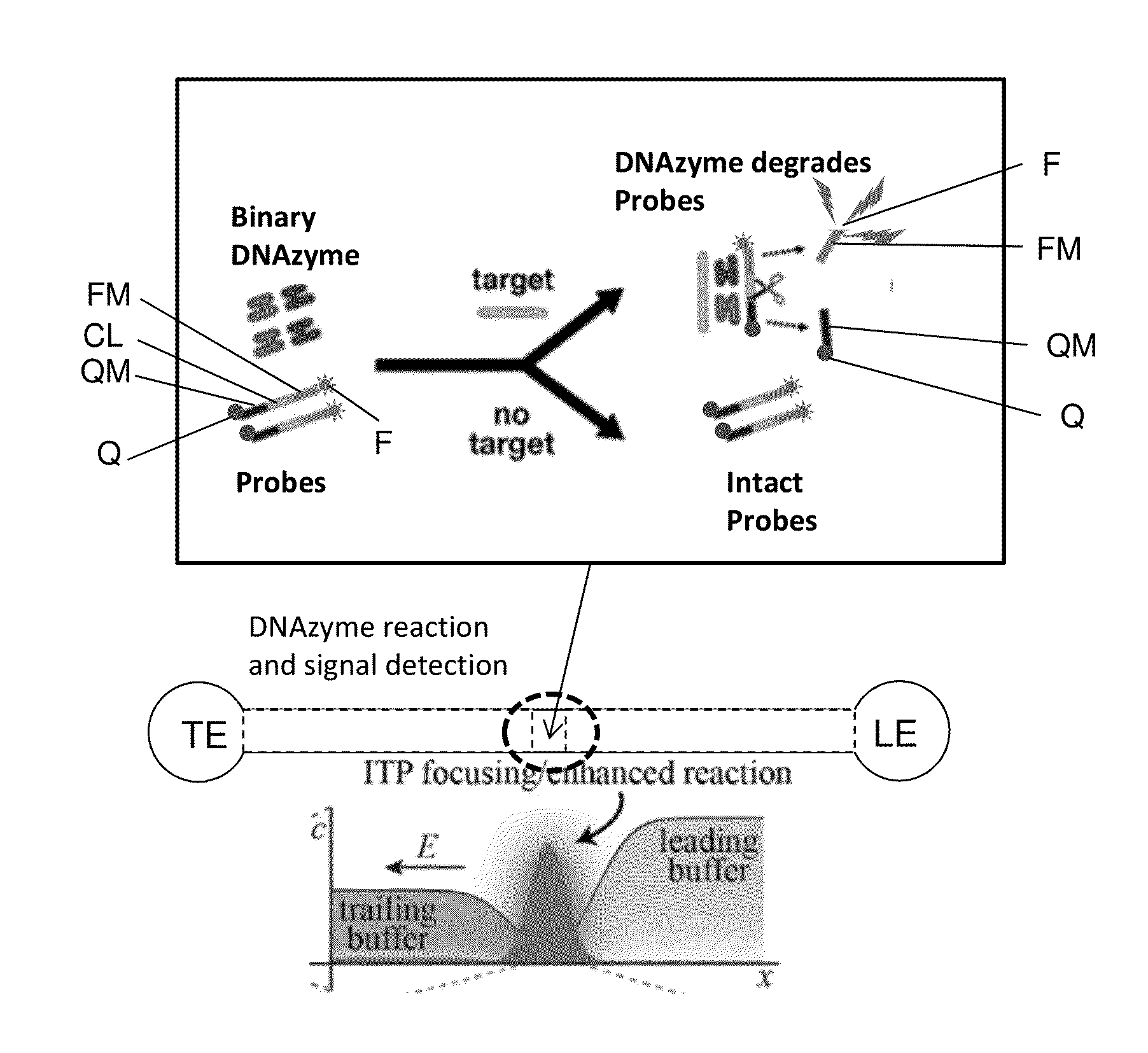
[0032]A first embodiment, shown in FIG. 6A, uses a binary DNAzyme and a probe, with simultaneous signal extraction. The binary DNAzyme (similar to the one shown in FIG. 5) has two parts; each part includes a target arm, a substrate arm, and a partial catalytic core. Initially in an inactive state where the two parts are separate, the binding of the respective target arms of the two parts to the target DNA forms the active binary DNAzyme structure, which can then hybridize to the probe and catalyze its cleavage. A FRET (Förster resonance energy transfer or fluorescence resonance energy transfer) quenching probe is used. The probe has three modules (see FIG. 6A): a quencher module QM modified by a quencher Q, a cleaved module CL capable of being cleaved by the binary DNAzyme activated by target sequences, and a fluorescent module FM modified by a fluorescent dye F. The cleaved module is located between the quencher module and the fluorescent module. The probe is capable of hybridizing...

second embodiment

[0037]A second embodiment, shown in FIG. 7A, uses a binary DNAzyme and a fluorescent probe with a probe capturing gel to accomplish separated signal extraction, where the location of signal extraction (detection) is separate from the location of the DNAzyme reaction. As shown in FIG. 7A, the probe has three modules: a capture module CAP capable of being captured by the capture gel, a cleaved module CL capable of being cleaved by the binary DNAzyme activated by target sequences, and a fluorescent module FM modified by a fluorescent dye F. The cleaved module is located between the capture module and the fluorescent module. The probe is capable of hybridizing to and being cleaved by the activated binary DNAzyme.

[0038]A sample containing target DNA sequences (or no target DNA sequence), the two DNAzyme subunits, and the probes are mixed, and the mixture is assayed using an on-chip ITP setup similar to that described in Garcia-Schwarz et al. Analytical Chemistry 2012 (see FIG. 3). Using ...

third embodiment

[0049]A third embodiment, shown in FIG. 8A, uses a binary DNAzyme and a fluorescent probe with a sieving matrix to accomplish separated signal extraction. The probe has three modules: a long module LM, a cleaved module CL capable of being cleaved by the binary DNAzyme activated by target sequences, and a short module SM modified by a fluorescent dye F. The cleaved module is located between the long module and the short module. The size difference between the intact probe and the short module is large enough to enable them to be separated by the sieving matrix in the microfluidic chip. The probe is capable of hybridizing to and being cleaved by the activated binary DNAzyme.

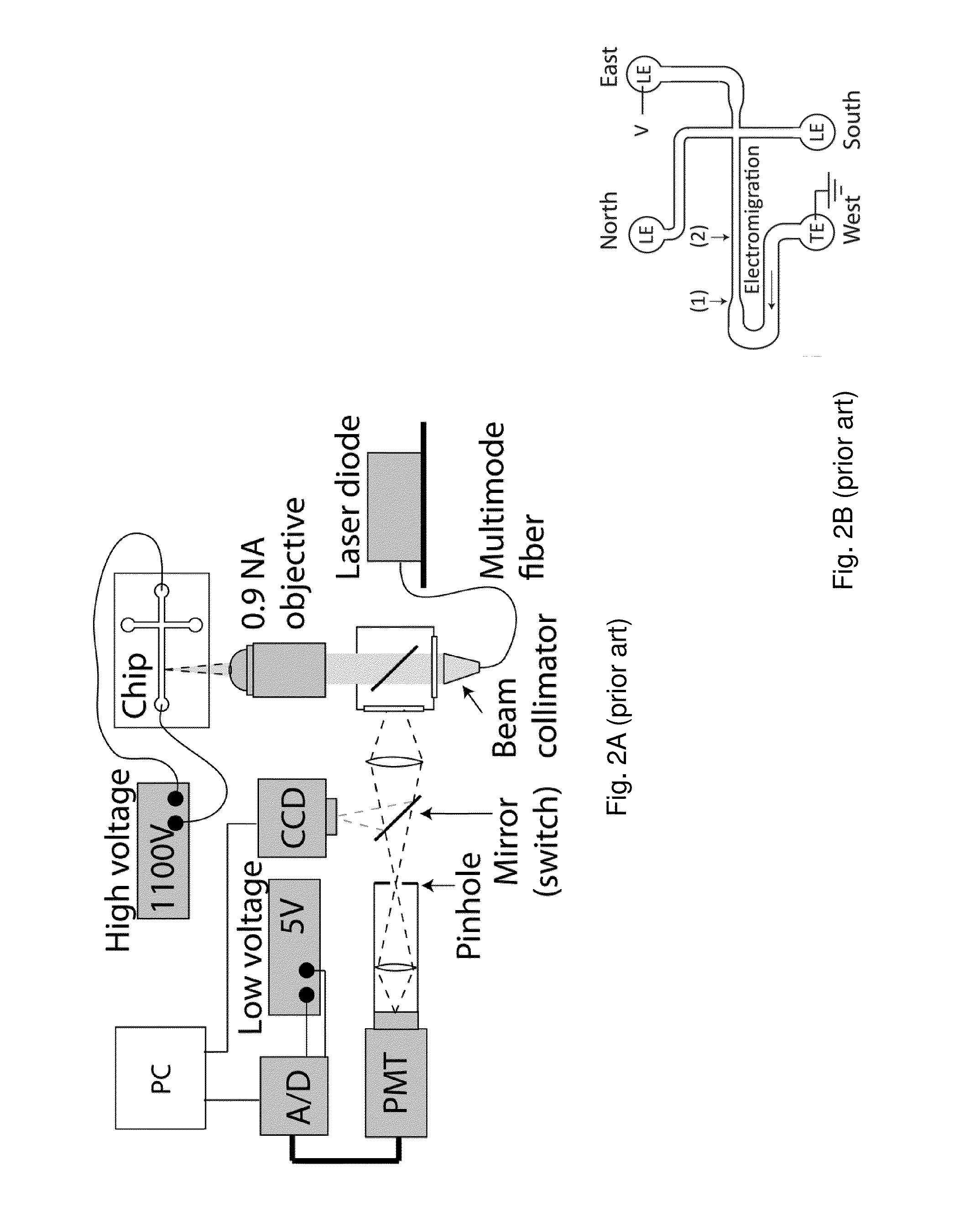
[0050]A sample containing target DNA sequences (or no target DNA sequence), the two DNAzyme subunits, and the probe are mixed, and the mixture is assayed using an on-chip ITP setup similar to that described in Eid et al. Analyst 2013. Using this setup, DNAzyme reaction takes place in the isotachophoresis condition,...


PUM

PropertyMeasurementUnit
reaction timeaaaaaaaaaa
fluorescentaaaaaaaaaa
voltageaaaaaaaaaa

Abstract

A DNA detection method combines DNAzyme reactions and on-chip isotachophoresis (ITP). A mixture of sample containing a target DNA and a DNAzyme sensor which is either (1) a catalytic molecular beacon or (2) a binary DNAzyme and a probe is loaded into a trailing electrolyte (TE) reservoir of a microfluidic chip. In the presence of the target DNA, the catalytic molecular beacon or the probe is cleaved to generate a fluorescent fragment. Enhanced DNAzyme reaction occurs at the TE-to-LE interface. Fluorescent signal from cleaved catalytic molecular beacon or probe is detected either at the location where DNAzyme reaction occurs or at a separate location. In the latter case, the microfluidic chip has a separation region containing a capture gel or a sieving matrix which allows the fluorescent fragment to pass through but captures or traps the uncleaved catalytic molecular beacon or probe.

Description

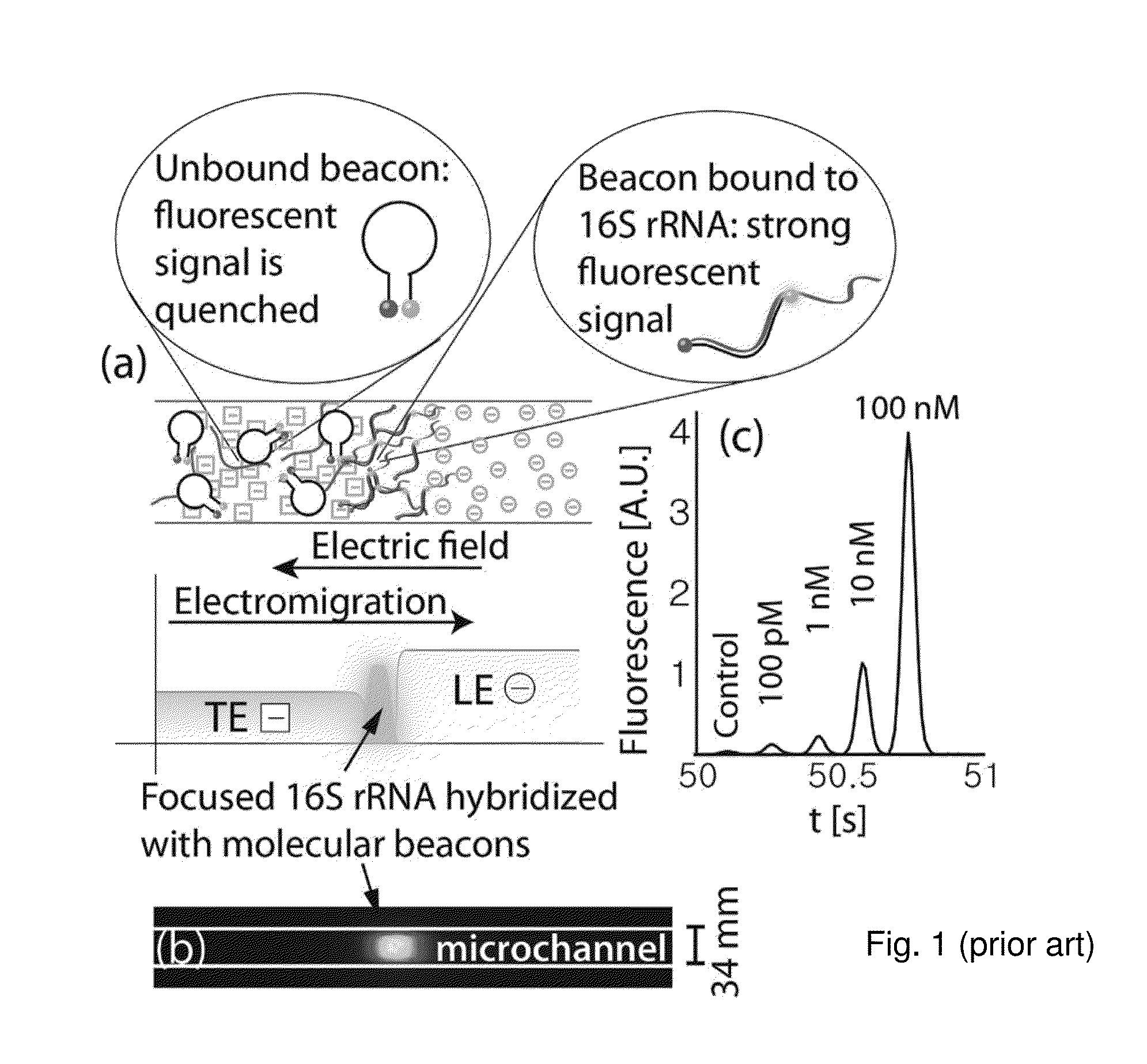
BACKGROUND OF THE INVENTION[0001]1. Field of the Invention[0002]This invention relates to DNA detection, and in particular, it relates to a DNA detection method that utilizes DNAzyme reactions and on-chip isotachophoresis (ITP).[0003]2. Description of Related Art[0004]Sensitive DNA detection techniques based on enzymatic amplification such as polymerase chain reaction (PCR) are widely used in diagnosis. However, they are time-consuming, complex (low robustness) and expensive.[0005]Isotachophoresis (ITP) is an electrophoresis technique that uses two buffers including a high mobility leading electrolyte (LE) and a low-mobility trailing electrolyte (TE). In peak-mode ITP, sample species bracketed by the LE and TE focus into a narrow TE-to-LE interface. Due to the high concentration of sample species in a small volume at the interface, high efficiency (rapid) molecular-molecular interaction can occur.[0006]An ultra-rapid nucleic acid detection technology using ITP is described in Rapid ...

Claims


Application Information

Patent Timeline
Patent Type & Authority Applications(United States)
IPC IPC(8): C12Q1/68
CPCC12Q1/6818C12Q1/6816C12Q2521/345C12Q2525/301C12Q2565/629
Inventor YAMAMOTO, NORIAKI
Owner KONICA MINOLTA LAB U S A INC
Learn More