In Situ Retorting of Hydrocarbons and Selected Metal

a hydrocarbon and in situ technology, applied in the field of in situ retorting of hydrocarbons and selected metals, can solve the problems of reducing the relative permeability of the formation, affecting the fluid flow of materials, and largely failing the practicality test of work

Inactive Publication Date: 2015-07-16
AFFHOLTER JOSEPH A +1
View PDF8 Cites 10 Cited by
  • Summary
  • Abstract
  • Description
  • Claims
  • Application Information

AI Technical Summary

Benefits of technology

[0009]Methods that reduce interfacial or surface tension, and the resulting impedance of flow that stems from it, are highly desirable in the field of hydrocarbon recovery and production. In situ methods for consolidating formation hydrocarbons into a single mobile fluid phase are of immense interest in the field of fuel and chemical production. It is also highly desirable to employ in situ methods that allow for production of formation hydrocarbons having a substantially narrower, and / or more defined, and / or more controlled range of compositions than is found using conventional petroleum and natural gas production technologies. Generally, methods that allow an operator increased control over the physical chemistry (including phase behavior) of formation fluids are of value in enhancing or enabling economic production. Similarly, methods that provide an operator with increased control of the chemical composition of the produced formation fluids are of great value provide opportunities to increase the value of the produced products.
[0011]The methods of this invention provide a means to produce fluid hydrocarbon from formations comprising one or more fixed bed carbonaceous deposits (FBCD), and for extending high levels of protection to the surrounding environment by a combination of aquifer and water management methods, low-impact surface processing facilities, and a low-density distribution of surface wells and equipment. The invention further comprises both methods and systems that enable physico-chemical transformation of a wide range of carbon-rich deposits in situ followed by recovery of at least a portion of the produced hydrocarbons and / or other product materials at the surface. The methods allow production of various categories of products including: linear and cyclic hydrocarbons, linear and cyclic olefins, aromatic hydrocarbons, and other non-hydrocarbon products derived from formation minerals. For example, molecular hydrogen, metals (e.g. rare earth, precious and others) and metal salts, and other non-carbonaceous products also may be produced.

Problems solved by technology

With a few exceptions, the work largely failed the test of practicality.
For example, differences in interfacial or surface tension between any two phases (and / or the materials within them) may interfere with the fluid flow of materials in one or more of these or other phases.
This impedance may result in reduced relative permeability of the formation to at least one fluid phase.
It may also reduce the effective permeability of the formation as a whole.
Other physical forces acting upon the multi-phase formation fluids also may impede mobility of such fluids in the formation.
Acting across a formation, these localized interfacial behaviors may result in substantial non-recoverable, residual oil saturation left behind after the relative permeability to oil has been reduced to a low value.
In heavy oil and tar sand deposits, differential viscosity and capillarity problems in multiphase flow are often even more significant than conventional formations, resulting in both very slow production rates and very high residual oil left behind after depletion, even when the formation is relatively porous or permeable.
Even after reducing interfacial tension and decreasing viscosity by steam heating, substantial volumes of this oil still remains non-recoverable at economic rates, based on such multiphase fluid flow.
Often, methods for developing formations containing substantially immobile hydrocarbon deposits fail the test of economic viability because they are not: a) effective at achieving high volumetric productivity, b) flexible with respect to in situ hydrocarbon chemistries and recovery methods, c) predictable and effective across a broad range of common geological formation conditions, or d) compatible with the effective protection of the surrounding environment and / or ecosystems.
Accomplishing this objective often requires methods that cause limited, but important changes in the chemical structure and / or physical state of the deposited resource in situ, i.e. in the formation.

Method used


Image

  • In Situ Retorting of Hydrocarbons and Selected Metal
  • In Situ Retorting of Hydrocarbons and Selected Metal
  • In Situ Retorting of Hydrocarbons and Selected Metal

Examples


example 1

Identification of Several Oil Shale Resource for Development Using the Systems and Methods of this Invention

[0099]Hydrodynamically-modulated, in-situ retorting of oil shale and other hydrocarbon formations may be conducted using the methods of this invention. In an embodiment, successful retorting of an oil shale formation may be accomplished while simultaneously protecting surrounding formation water from leakage of fluids from the retort-treated portion of the formation. In one embodiment, surrounding aquifers may be protected using hydrodynamic-flow barriers. Use of such containment methods are preferred in areas where the natural aquifers' potentiometric surface is at least 200 ft higher than the elevation of the aquifers in the target formation. To this end, preferred, oil shale resource area selected for in situ retorting and / or treatments comprising this invention are those containing high-permeability, natural aquifers through which thermal-energy carrier fluid (TECF) may be...

example 2

Characterization and Development of a Carbonaceous Oil Shale Formation Exemplified in the Piceance Basin of Colorado

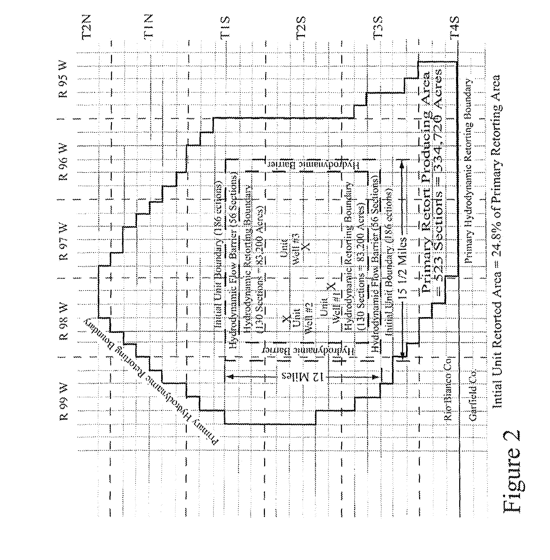
[0105]In a specific embodiment, the methods of this invention are applied to the development and in situ retorting of the oil shale formation in the Piceance Basin. As shown in FIG. 2, a preferred portion of the basin is located substantially within Rio Blanco County Colorado, between coordinates ranging from R 99 W-to-R 95 W, and T 2 N-to-T 4 S. FIG. 1 illustrates an approximately 12 mile by 15½ mile segment of this basin representing the core unitized (e.g. target) area for application of this in situ retorting method. As shown in the FIG. 1 (inner-most dashed box), this target area comprises approximately 130 sections, or about 83,200 acres. This propped, unitized, active retort area is surrounded by a hydrodynamic barrier (shown as the outer-most dashed box) comprising about an additional 56 sections, of the resource area. Within the unitized retort area, proposed ...

example 3

Mobilization of Hydrocarbon and Other Materials from Various Lithologic Layers

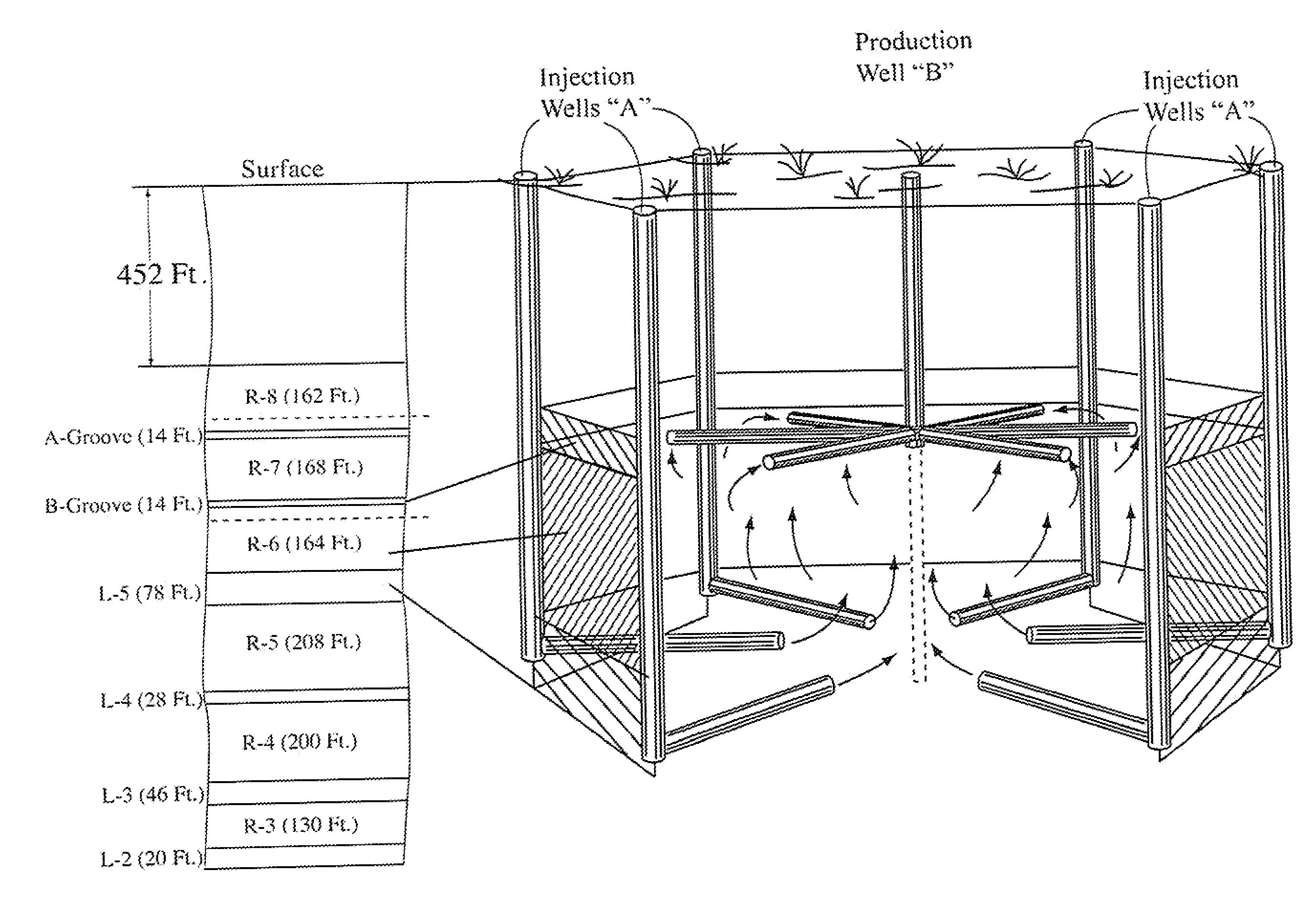
[0117]FIG. 5 illustrates the approximate stratigraphic column of the oil-shale zone as typically occurring at locations near the center and deeper portion of the Piceance Basin (i.e., Sect. 36, T2 S, R98W). A cross-section of the formation showing depths and thicknesses of various deposits is shown on the left of FIG. 5. An expanded view of the portion of the formation (e.g. depths of about 590 ft to about 840 ft) containing the A-Groove, B-Groove and R-7 stratigraphic zone is shown on the right. The zones labeled R-8, R-7, R-6, R-5, R-4, R-3, etc. are relatively rich zones containing relatively large quantities of kerogen and relatively small amounts of porous zones or “voids” (open holes) left in the rock after the soluble minerals have been dissolved by hydrodynamically flowing formation water. Consequently, these “R”-designated (i.e., “R-rated”), oil-shale zones have relatively few aquifers, and any ex...


PUM


Abstract

A method of producing hydrocarbons in situ from a fixed-bed hydrocarbon formation disposed below a ground surface and having a higher permeability zone substantially parallel to, and between a top lower permeability zone and a bottom lower permeability zone. The steps include providing at least one injection well and first and second production wells in the higher permeability zone, injecting a heated thermal-energy carrier fluid (TECF) into the injection well, circulating the carrier fluid through the zone and creating a substantially horizontal situ heating element (ISHE) between the injection well and the production wells for mobilizing the hydrocarbons.

Description

[0001]This non-provisional, Continuation patent application claims the benefit of a CIP patent application, Ser. No. 13 / 471,862, filed on May 16, 2012. This CIP patent application claims the benefit of a non-provisional CIP patent application, Ser. No. 13 / 317,604, filed on Oct. 25, 2011 and a CIP patent application, Ser. No. 13 / 068,423, filed on May 11, 2011. These two prior CIP patent applications claim the benefit of an earlier filed Parent patent application Ser. No. 11 / 455,438, filed on Jun. 19, 2006, now U.S. Pat. No. 7,980,312 and published on Jul. 19, 2011. The Parent patent application claims the benefit of an earlier filed Provisional patent application, Ser. No. 60 / 692,487, filed on Jun. 20, 2005, by the subject inventors.BACKGROUND OF THE INVENTION[0002]1. Field of the Invention[0003]The present invention relates generally to methods and systems for the production of hydrocarbons, hydrogen, water, industrial raw materials, as well as rare earth and precious metals, basic ...

Claims


Application Information

Patent Timeline
Patent Type & Authority Applications(United States)
IPC IPC(8): E21B43/24E21B43/243E21B43/30E21B41/00
CPCE21B43/24E21B43/305E21B43/243E21B41/0092E21B43/162
Inventor AFFHOLTER, JOSEPH A.HILL, GILMAN A.
Owner AFFHOLTER JOSEPH A
Why Eureka
Try Eureka