Narrow bandwidth laser device with wavelength stabilizer

a laser device and narrow bandwidth technology, applied in the field of laser devices, can solve the problems of difficult decoding of optical signals at optical receiving terminals, difficult to achieve optical transmission to 5 km in some cases, and difficult to achieve 10 gbps class to 10 km or more, etc., to achieve high-speed long-distance communication, low transmittance, and low manufacturing cost of optical elements

Active Publication Date: 2015-07-16
PHOVEL
View PDF8 Cites 12 Cited by
  • Summary
  • Abstract
  • Description
  • Claims
  • Application Information

AI Technical Summary

Benefits of technology

[0038]The present invention has an effect that in laser light for optical communication having a high-speed modulation signal over the 2.5 Gbps class or 10 Gbps class, a TO type package, which is inexpensive in comparison to a butterfly type or a mini flat type package housing and enables high-speed long-distance communication by inserting a wavelength-selective filter that performs selection such that a signal corresponding to a “1” signal is large and laser light corresponding to a “0” signal has low transmittance, is effectively used, so...

Problems solved by technology

This phenomenon is more serious, particularly when a bit rate is high and the transmission distance is large, and accordingly, optical transmission of an optical signal generated in a semiconductor laser at a band of 1550 nm driven in the 10 Gbps class to 10 Km or more is very difficult and even optical transmission to 5 Km is difficult in some cases.
When the ER is low, “1” and “0” signal are mixed at an optical receiving terminal due to chirp in a semiconductor laser diode chip and dispersion in an optical fiber, so it b...

Method used


Image

  • Narrow bandwidth laser device with wavelength stabilizer
  • Narrow bandwidth laser device with wavelength stabilizer
  • Narrow bandwidth laser device with wavelength stabilizer

Examples


Embodiment Construction

[0055]Preferred embodiments not limiting the present invention will be described hereafter in detail with reference to the accompanying drawings.

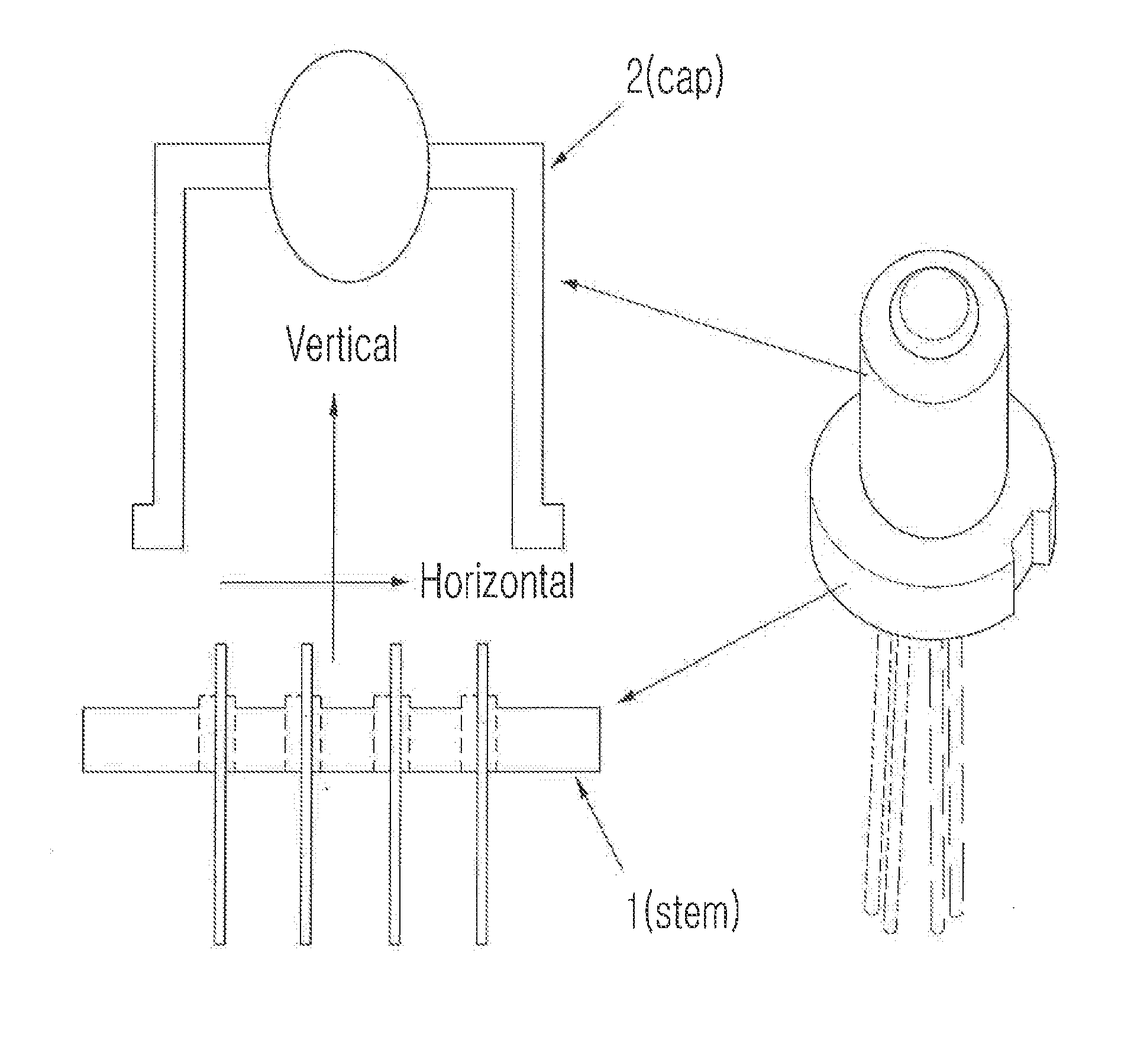
[0056]FIG. 1 is a diagram schematically illustrating a TO type package that is applied to the present invention.

[0057]As illustrated in FIG. 1, the TO type package includes a stem 1 and a cap 2, in which parts are disposed on the bottom of the stem 1 and then sealed by the cap 2. In this structure, laser light is discharged out of the TO type package through a through-hole formed through the top of the cap 2. In general, the through-hole of the cap 2 is sealed by a lens or a flat glass. In FIG. 1, a vertical direction and a horizontal direction to be used for describing the present invention are defined by arrows.

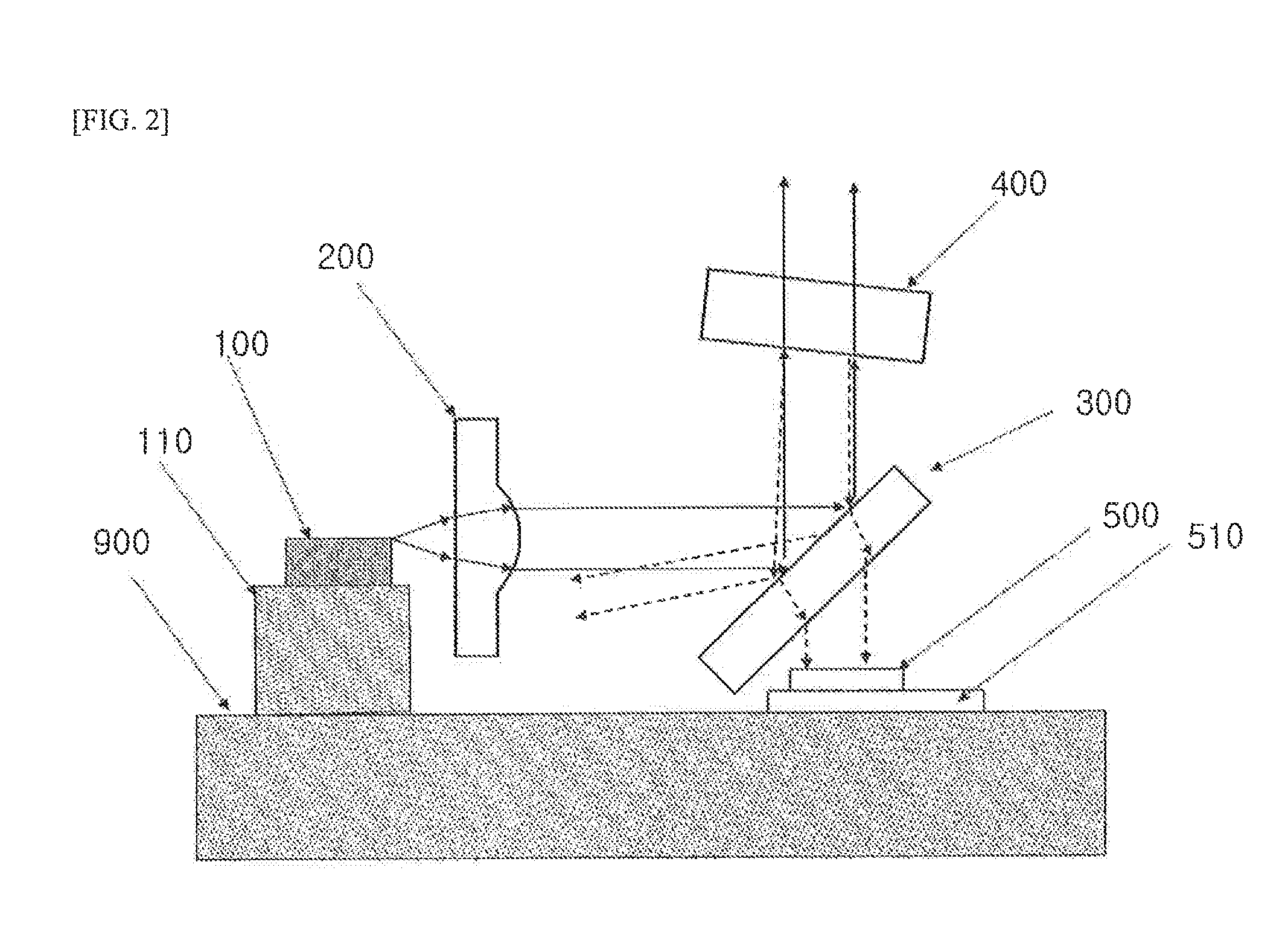
[0058]FIG. 2 is a conceptual diagram illustrating the operation principle of an optical element that can transmit an optical signal, for example, in the 10 Gbps class to a long distance by mounting a semiconductor laser diode chip ...


PUM


Abstract

A TO type laser device that can perform long-distance transmission due to a reduced line breadth of laser light. A semiconductor laser device which comprises a laser diode chip (100) that emits laser light; a wavelength-selective filter; a collimating lens (200) disposed in a light path between the laser diode chip (100) and the wavelength-selective filter and to collimate light emitted from the laser diode chip (100); a 45°-partial reflective mirror (300) disposed in a light path between the laser diode chip (100) and the wavelength-selective filter for changing laser light traveling parallel to the bottom of a package into laser light traveling perpendicularly to the bottom of the package; and an optical wavelength supervisory photodiode (500) disposed in a light path along which laser light reflecting from the wavelength-selective filter, after being emitted from the laser diode chip (100), passes through the 45°-partial reflective mirror (300).

Description

CROSS-REFERENCE TO RELATED APPLICATION(S)[0001]This application claims the benefit under 35 U.S.C. §119(a) of International Patent Application No. PCT / KR2014 / 004203, filed on May 12, 2014, the entire disclosure of which is incorporated herein by reference for all purposes.FIELD OF THE INVENTION[0002]The present invention relates to a laser device, particularly a laser device with a wavelength stabilizer that includes a wavelength stabilizer, can be subminiaturized, and can perform long-distance transmission due to reduction in line breadth of laser light emitted from a package.BACKGROUND OF THE INVENTION[0003]Recently, communication services with large communication capacity, including video service for smartphones, have been provided. Accordingly, there is a need for greatly increasing the existing communication capacity, and as a method of greatly increasing communication capacity, there are a method of increasing the bit rate used for optical communication and a WDM (wavelength d...

Claims


Application Information

Patent Timeline
IPC IPC(8): H04B10/50H01S5/022H01S5/0687
CPCH04B10/503H01S5/02292H01S5/0687H01S5/02212H01S5/02415H01S5/06837H01L2224/48091H01L2224/48137H01L2224/45144H01S5/02255H01S5/02325H01L2924/00014H01L2924/00
Inventor KIM, JEONG-SOO
Owner PHOVEL
Why Eureka
Try Eureka