Machine and method for powder-based additive manufacturing

Active Publication Date: 2015-07-23
MICHELIN & CO CIE GEN DES ESTAB MICHELIN +1
View PDF7 Cites 72 Cited by
  • Summary
  • Abstract
  • Description
  • Claims
  • Application Information

AI Technical Summary

Benefits of technology

[0015]It is therefore an objective of embodiments of the invention to alleviate at least one of the disadvantages described hereinabove and to propose a machine and a method for powder-based additive manufacture of a three-dimensional object

Problems solved by technology

The disadvantages of this solution are connected with the fact that the object is manufactured inside a container which additionally contains the drive means, which means that it is heavier, bulkier and therefore more difficult and more expensive to transport.
On top of that, this container needs to be positioned very precisely facing each workstation of the machine, because if it is not, there is a risk that errors in the geometry of the manufactured object will appear.
The disadvantages with this configuration are the substantial bulk and weight of the container that is to be transported.
The disadvantage with this configuration is that it calls for the plate to be actuated in cantilever fashion, which places a great deal of stress on the actuating arm, particularly when the powder is being compressed or when components of large dimensions are being built.
Moreover, complex sealing means need to be arranged at the vertical slots in order to prevent powder from escaping out of the container.
On top of that, detaching the platform from the container and mounting a new platform are operations that are fairly tricky, as the platform needs to be positioned very precisely with respect to this container.
Leaving aside the fact that it is actuated by a cantilever system as in the p

Method used


Image

  • Machine and method for powder-based additive manufacturing
  • Machine and method for powder-based additive manufacturing
  • Machine and method for powder-based additive manufacturing

Examples


Embodiment Construction

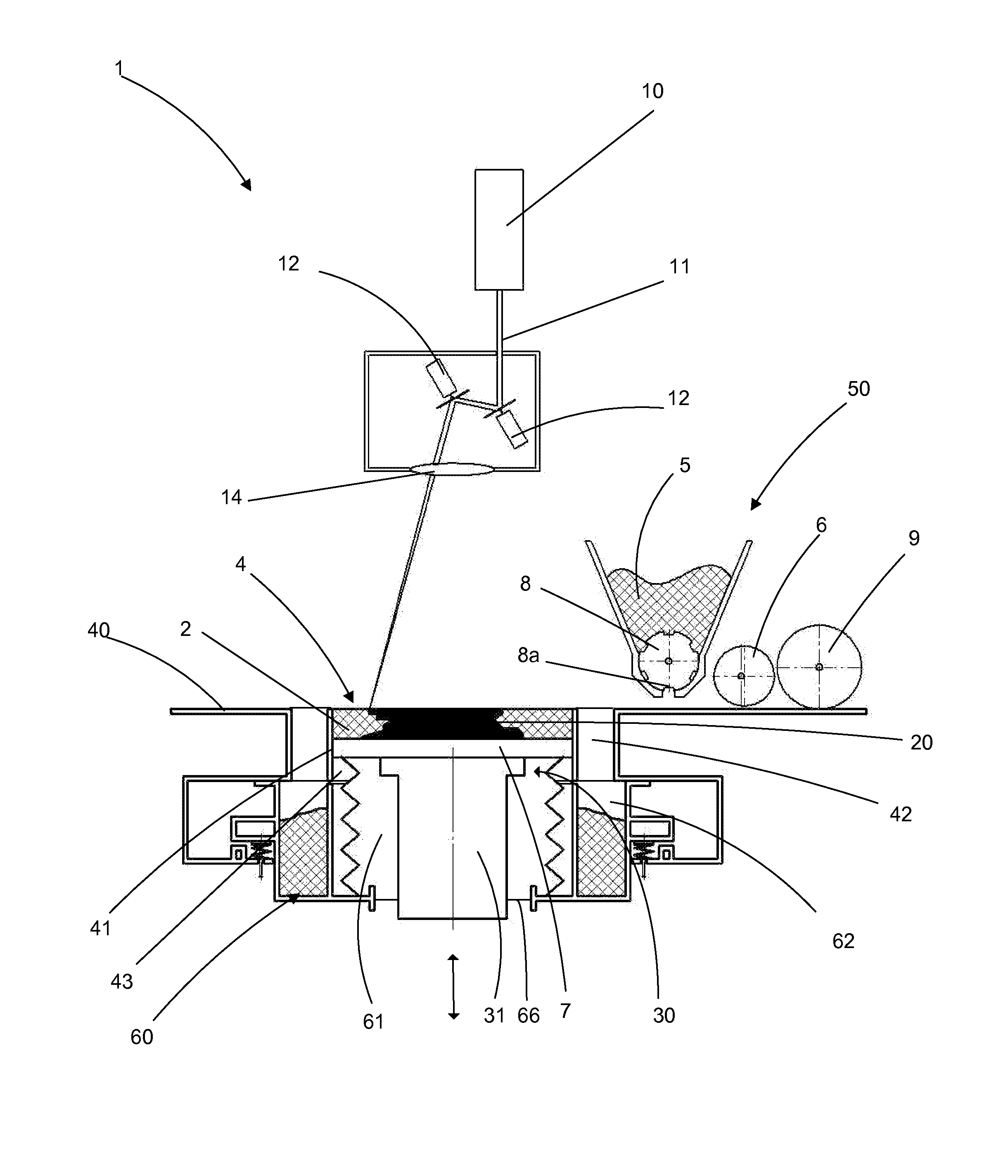
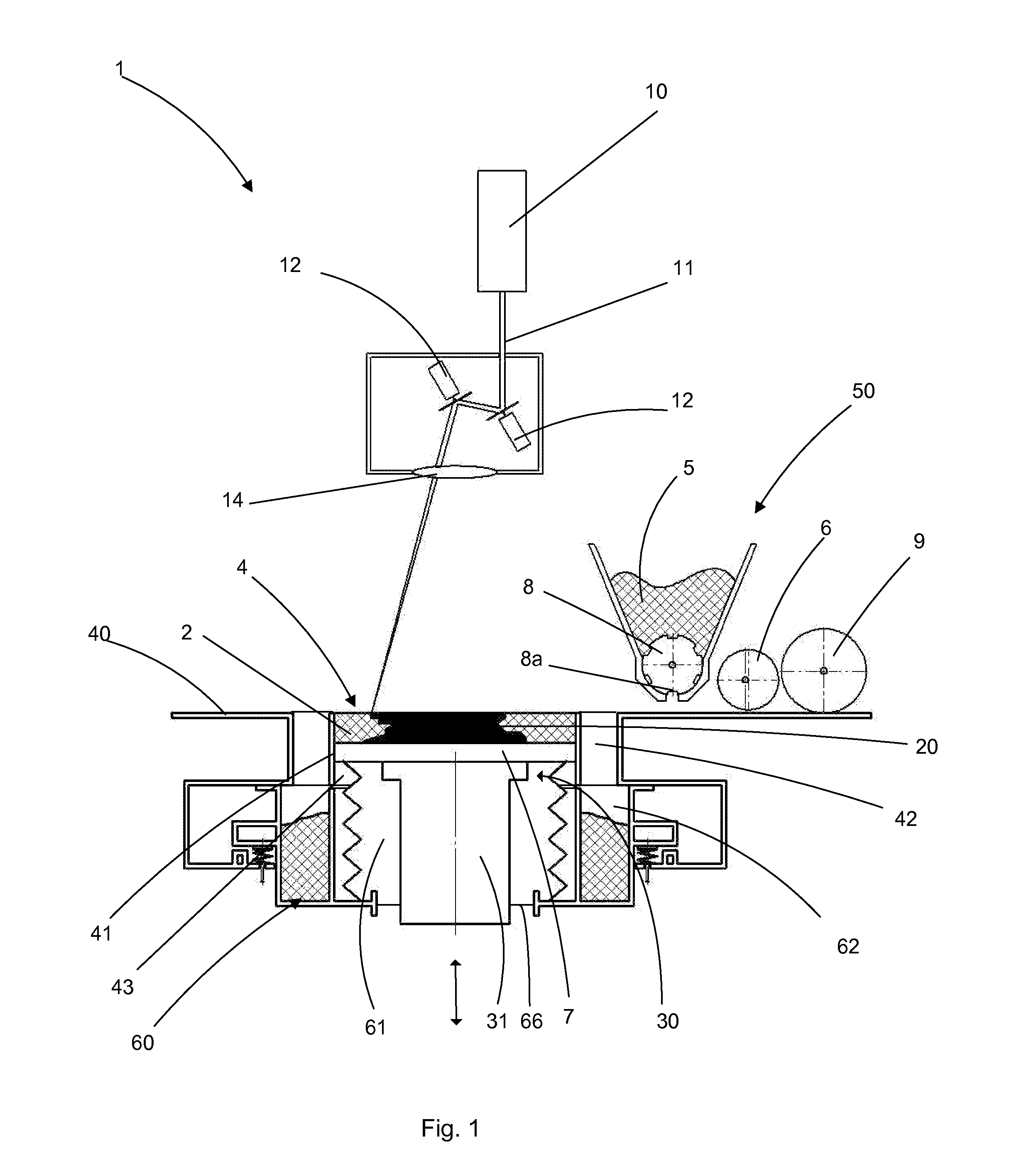
[0063]FIG. 1 schematically depicts one exemplary embodiment of a machine 1 for the additive manufacture of a component 20. As described in the preamble for the application, the invention in actual fact applies to all types of powder-based additive manufacture using the sintering or total melting of the particles of the said powder using a beam of energy such as an electromagnetic radiation (for example a laser beam) or a beam of particles (for example an electron beam).

[0064]An energy source, in this instance a laser source 10, emits a laser beam 11 the orientation of which is controlled by galvanometric mirrors 12. An optical lens 14 allows the beam 11 to be focused on the working zone 4 so as to heat the top layer of the powder 2 in a precise pattern and thus selectively cause the powder to melt. After one layer of powder has been treated by the laser beam, the build plate 7 is lowered by a unit thickness (which corresponds to that of a layer of powder) and is covered with a new l...


PUM

PropertyMeasurementUnit
Flexibilityaaaaaaaaaa
Energyaaaaaaaaaa
Sliding frictionaaaaaaaaaa

Abstract

Machine for the additive manufacture of a three-dimensional object by sintering or melting powder using a beam of energy acting on a layer of powder in a working zone, the said working zone being defined in the upper part
    • of a build sleeve fixedly mounted in a chassis, in which sleeve the said object is manufactured, the said object being supported by
    • a build plate which slides inside the said build sleeve when driven in vertical translation by
    • the head of an actuating cylinder placed along the central axis of the said sleeve. The build plate is positioned inside a transport container which is arranged removably between the said sleeve and the said actuating cylinder,
    • the machine comprises means for moving the transport container (60) vertically into contact with the build sleeve and
    • the container is open at its top and at its bottom so that, when the actuating cylinder is actuated, the head thereof can transfer the said plate between the said transport container and the said build sleeve which forms a build envelope around the said plate.

Description

[0001]This application is a 371 national phase entry of PCT / EP2013 / 066130, filed 31 Jul. 2013, which claims benefit of French Patent Application No. 1257415, filed 31 Jul. 2012, the entire contents of which is incorporated herein by reference for all purposes.BACKGROUND[0002]1. Field[0003]The disclosure relates to machines and methods used in powder-based additive manufacturing by sintering or melting particles of the said powder using a beam of energy, such as an electromagnetic radiation (for example a laser beam), or a beam of particles (for example an electron beam). Such a powder-based additive manufacturing method leads to a successive, layer by layer, consolidation, using a beam of energy or particles, of the selected zones of a stratum of pulverulent material, the consolidated zones corresponding to successive sections of the three-dimensional object.[0004]More specifically, the disclosure relates to the means and methods used for transferring a three-dimensional object betw...

Claims


Application Information

Patent Timeline
IPC IPC(8): B22F3/105B23K15/00B23K26/34B22F3/00B28B1/00
CPCB22F3/1055B22F3/003B28B1/001B23K26/345B22F2003/1058B33Y10/00B33Y30/00B22F2003/1056B23K15/0086B23K26/342B29C64/153B29C64/245B29C64/232B29C64/25Y02P10/25B22F12/49B22F12/52B22F10/73B22F12/63B22F10/28B22F12/222
Inventor PIALOT, FREDERICTORRES-CATELLANO, MIGUELWALRAND, GILLESPOURCHER, BENOIT
Owner MICHELIN & CO CIE GEN DES ESTAB MICHELIN
Why Eureka
Try Eureka