Optical projection system and image projector incorporating the same

Active Publication Date: 2015-07-23
RICOH KK
View PDF7 Cites 18 Cited by
  • Summary
  • Abstract
  • Description
  • Claims
  • Application Information

AI Technical Summary

Benefits of technology

[0009]The present invention aims to provide a compact, short projection-distance optical projection system including a free-form surface lens whi

Problems solved by technology

However, distortion and field curvature are corrected only with the free-form surface mirror, which brings enlargement of the size of the mirror.
However, related art h

Method used


Image

  • Optical projection system and image projector incorporating the same
  • Optical projection system and image projector incorporating the same
  • Optical projection system and image projector incorporating the same

Examples


first example

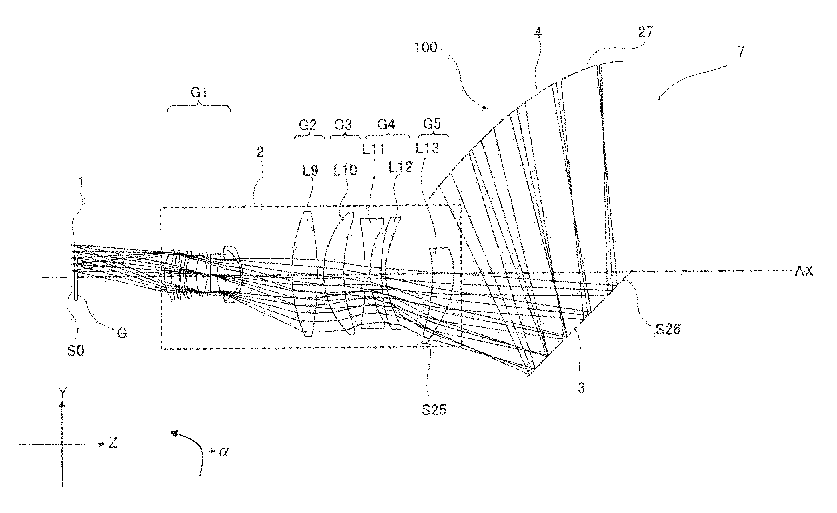
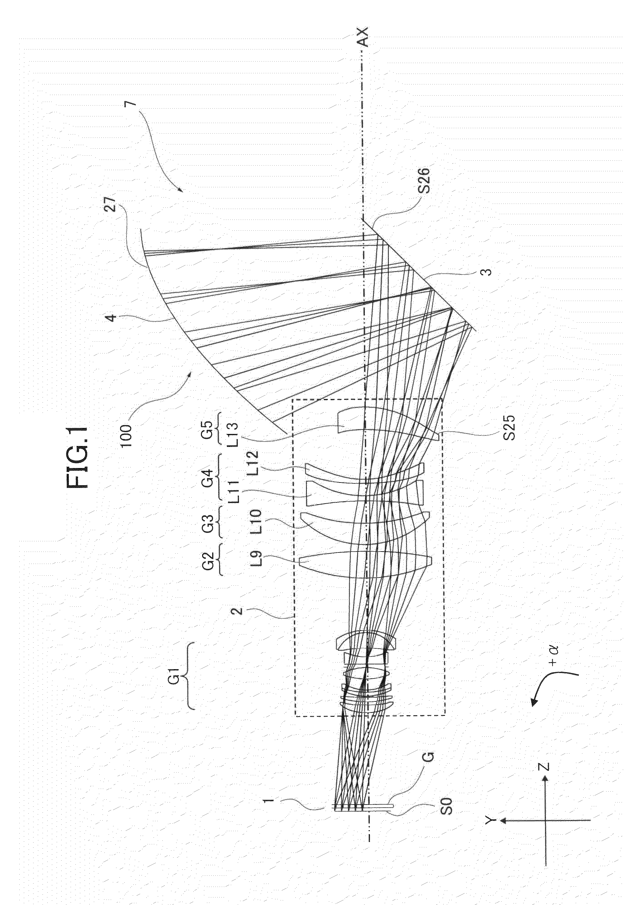
[0051]Next, specific values of the optical projection system 100 according to first embodiment are described by way of example. In the following, unit of a length is mm unless otherwise noted. The numerical aperture of the object side of the first optical system 2 is 0.195. The size ratio of an image displayed on the surface S0 of the image display element 1 is 10 (vertical or in Y-direction): 16 (horizontal or in X-direction) and width across corner is 0.65 inches (165 mm). The optical axis of the first optical system 2 is offset from the center of the surface S0 by 1.541 mm in −Y-direction. The optical property of each optical element of the optical projection system 100 is shown in the following Table 1. The codes in Table 1 represent as follows.

S0 to S30: surface numbers

R: curvature radius

D: surface interval

Nd: refractive index of d-line

vd: Abbe number

DA to DD: variable intervals

TABLE 1RndFACECURVATUREDREFRACTIVEvdNO.RADIUSINTERVALINDEXDISPERSIONS0inf30.00 S1 *17.6282.401.515063...


PUM


Abstract

An optical projection system enlarges an image on an image display element and projects the enlarged image onto a screen. The system includes the image display element, a first optical system including lens groups arranged in order from an image display element side, a lens barrel holding the lens groups, and a free-form surface lens rotationally asymmetric and made from plastic, and a second optical system including a curved mirror disposed after the first optical system, wherein the free-form surface lens is formed to decrease in thickness from an intersection point between a surface of the free-form surface lens and an optical axis of the first optical system to an outer periphery of the lens along a line extending to the outer periphery.

Description

CROSS REFERENCE TO RELATED APPLICATION[0001]The present application is based on and claims priority from Japanese Patent Application No. 2014-007687, filed on Jan. 20, 2014, the disclosure of which is hereby incorporated by reference in its entirety.BACKGROUND OF THE INVENTION[0002]1. Field of the Invention[0003]The present invention relates to an optical projection system for projecting an enlarged image of an image displayed on an image display element onto a projection plane such as a screen as well as to an image projector incorporating such an optical projection system.[0004]2. Description of the Related Art[0005]An image projector comprises a lamp as a light source, an image display element such as a light valve including a DMD (Digital Micromirror Device) or a crystal liquid display panel, and an optical projection system. The display of the image display element is illuminated with a light beam from the lamp and an enlarged image of an image on the display surface is project...

Claims


Application Information

Patent Timeline
IPC IPC(8): G02B27/00G02B17/08G02B7/02G03B21/28
CPCG02B27/0025G03B21/28G02B27/0006G02B7/021G02B17/08G02B13/18
Inventor ARAI, NOBUYUKI
Owner RICOH KK
Why Eureka
Try Eureka