

Landing gear drive systems
- Summary
- Abstract
- Description
- Claims
- Application Information
AI Technical Summary
Benefits of technology
Problems solved by technology
Method used
Image


Examples
first embodiment
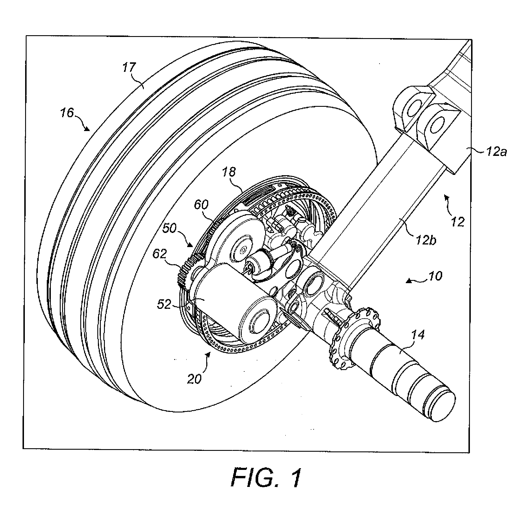
[0048]the invention is shown in FIGS. 1 to 8. In the illustrated embodiment the landing gear has two wheels, but the principles of the embodiment may be applied to landing gear with four or more wheels. The embodiment shows a main landing gear (i.e. a landing gear attached to wing structure or fuselage structure in the region of the wings), since the weight supported by the main landing gear is considered to provide the best traction between the wheels and the ground to enable reliable aircraft ground taxiing. However, the drive system of the present invention may alternatively be applied to a nose landing gear (i.e. a steerable landing gear towards the nose of the aircraft).
[0049]The landing gear 10 includes a telescopic shock-absorbing main leg 12, including an upper telescopic part 12a (main fitting) and a lower telescopic part 12b (slider). The upper telescopic part 12a is attached to the aircraft fuselage or wing (not shown) by its upper end (not shown). The lower telescopic pa...
third embodiment
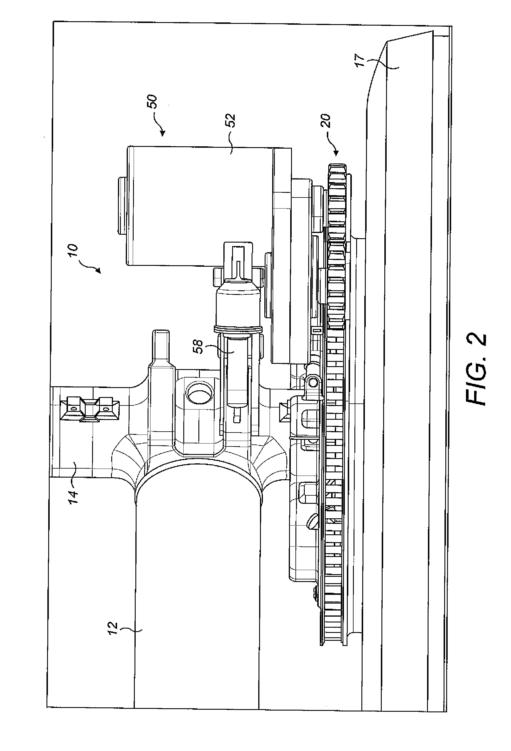
[0068]In the third embodiment the drive system 50 is capable of driving one of the wheels 16 of the two wheel landing gear, whilst the other wheel is not driven. For landing gear with more than two wheels a plurality of the drive systems 50 may be provided.
[0069]The drive system 50 of the third embodiment comprises a motor 52 coupled to an epicyclic gearbox 86 which rotates the first sprocket 60. The axis of rotation of the first sprocket 60 is co-axial with the motor axis of rotation. Whilst the overall axial length of the drive system 50 of the third embodiment is longer than the drive systems of the first and second embodiments, due to the eplicyclic gearbox 86, this is not problematic as only one wheel 16 of the landing gear is driven. By contrast, in the first and second embodiments, the axial length of drive system is comparably shorter in order that both wheels 16 of the landing gear may be driven by respective drive systems.
[0070]Of course, an epicyclic gearbox may be used i...
PUM
 Abstract
Description
Claims
Application Information