
Composite hanger grid and components, splash bar, assembly thereof and method of assembly

a technology of composite hanger and components, applied in the field of composite, can solve the problems of exposing the wire to corrosion, ultimately failing the wire, and similar local degradation of the material, and associated failure mechanisms

Active Publication Date: 2015-07-30
BRENTWOOD INDS
View PDF13 Cites 15 Cited by
  • Summary
  • Abstract
  • Description
  • Claims
  • Application Information

AI Technical Summary

Benefits of technology

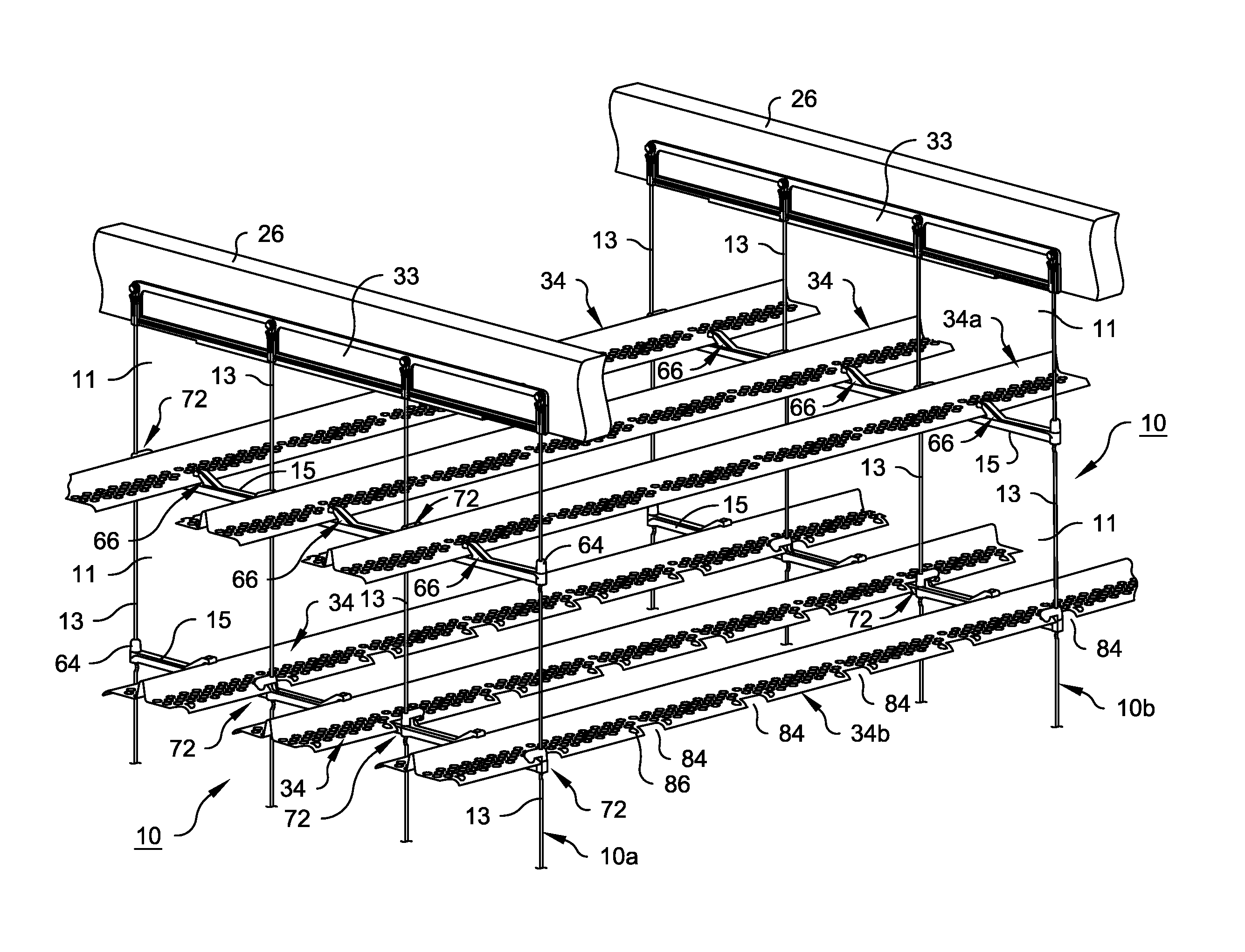
The present invention concerns a splash bar that can be supported on a horizontal beam and retained against dislodgement in windows defined by the horizontal beams and vertical members in a hanger grid. The splash bar is an elongated object with a longitudinal axis, top, bottom, front end, back end, length, and width. It has two side edges, one of which is free of openings and can slide freely on the horizontal beams. The other side edge has slots parallel to the length of the splash bar and located where the windows of adjacent hanger grids are located. The splash bar also has locking structures on its front and back sides that interlock with the slots and the bearing surfaces of the hanger grid, preventing the splash bar from dislodging longitudinally or vertically in the window. This invention provides a secure and stable support for the splash bar, ensuring its stability during installation and use.

Problems solved by technology

One treated version uses a dipped plastic coating; however, the vibration and movement of the splash bars within the tower from air flow causes localized wearing of the coating at contact points between the grid and the splash bar, thereby exposing the wire to corrosion and ultimately failure of the wire.
The second treated version uses galvanized metal; however, chemical treatment erodes the zinc coating leading to a similar local degradation of the material and associated failure mechanism as the coated wire mesh.
Stainless steel wire mesh is also used; however, the spot welded connection is typically limiting in its structural capacity and is the point of failure for this application.
The current plastic products attach via holes in the vertical members, concentrating the stress at these locations therefore further reducing the strength of the product.
There are problems regarding the installation and retention of the splash bars on the horizontal members.
The process of rotating the splash bars in the narrow windows during installation complicates and increases the time required for installation.
The method of attachment is critical in maintaining the splash bars in position and can have a significant impact on cost due to manpower required to attach the splash bar to the support at every grid location.
This leaves the unattached end of the splash bar to move freely within the grid windows due to the lateral and vertical air flow required for mass transfer.
The load of multiple panels connected together is then applied to the spot welds of the top horizontal wire which may end in failure of the welds, particularly in cold climates where ice may form on the hanger grids and splash bars in winter.
The same principle of accumulated load of multiple connected panels also applies to the plastic panels which results in the load surpassing the ultimate strength of the plastic vertical members.

Method used


Image

  • Composite hanger grid and components, splash bar, assembly thereof and method of assembly
  • Composite hanger grid and components, splash bar, assembly thereof and method of assembly
  • Composite hanger grid and components, splash bar, assembly thereof and method of assembly

Examples


Embodiment Construction

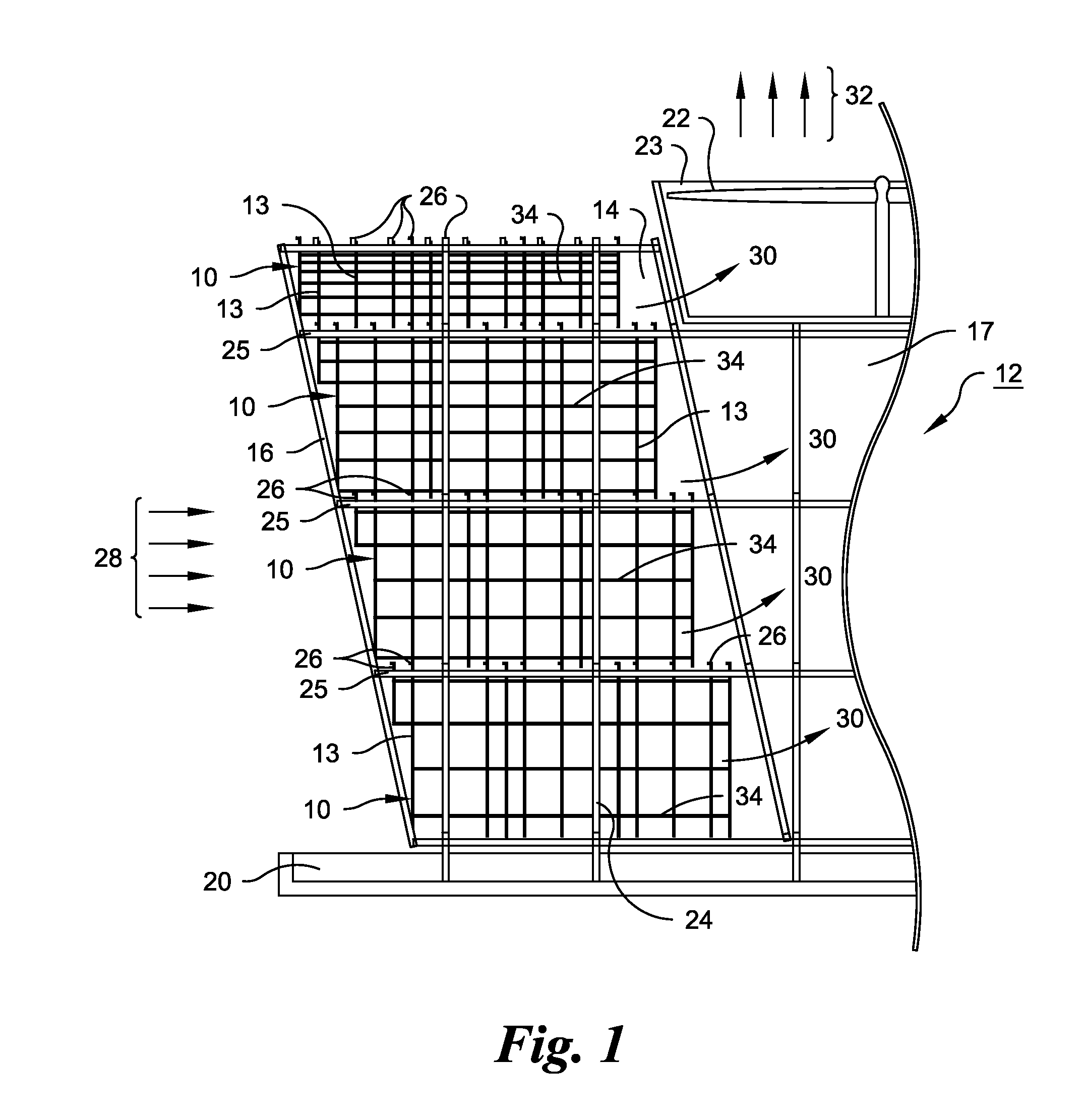
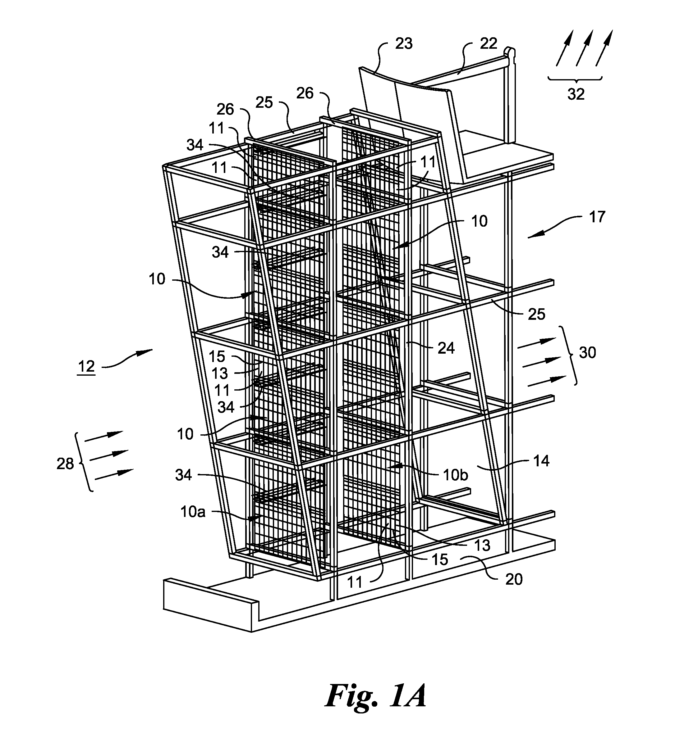
[0063]FIGS. 1 and 1A show various typical arrangements of hanger grids 10 according to embodiments of the present invention within schematic representations of a typical cross-flow cooling tower 12. The hanger grids, splash bars and assemblies thereof could be used as an evaporative cooler fill in any type of cooling tower, such as a concurrent, counter-current or cross-flow cooling tower, and are typically most often used in cross-flow cooling towers such as cooling tower 12.

[0064]The cross-flow cooling tower 12 has a pair of fill sections 14, only one of which is shown, adjacent to a central plenum 17. The hanger grids 10 are arranged in any desired configuration within the fill section 14, such as side to side of the fill section 14 or the cooling tower 12 as shown in FIGS. 1 and 1A, or front to back of the fill section 14 or the cooling tower 12, or at any oblique angle to the front, back or sides of the fill section 14 or cooling tower 12. Air enters the fill section 14 through...


PUM

PropertyMeasurementUnit
angleaaaaaaaaaa
angleaaaaaaaaaa
lengthaaaaaaaaaa

Abstract

A composite hanger grid for supporting splash bars in a cooling tower uses separate vertical suspension members and horizontal beams by which all of the operational loads imposed on the splash bars are transferred to the horizontal beams, which then transfer the load to the vertical suspension members. Since all of the horizontal beams are independent of each other and separate components from the vertical suspension members, the horizontal beams will be loaded equally throughout the entire hanger grid. Also disclosed are components of the composite hanger grid, splash bars adapted for use with specific embodiments of the composite hanger grid, assemblies of the composite hanger grid with its supported splash bars, a method of assembling a composite hanger grid and a method of assembling an evaporative cooler fill assembly, including hanger grids and splash bars, in a cooling tower.

Description

CROSS-REFERENCE TO RELATED APPLICATIONS[0001]Not applicableSTATEMENT REGARDING FEDERALLY SPONSORED RESEARCH OR DEVELOPMENT[0002]Not applicableREFERENCE TO A MICROFICHE APPENDIX[0003]Not applicableBACKGROUND OF THE INVENTION[0004]The present invention relates to a composite hanger grid for supporting splash bars in a cooling tower, components of the composite hanger grid, splash bars adapted for use with specific embodiments of the composite hanger grid, assemblies of the composite hanger grid with its supported splash bars, a method of assembling a composite hanger grid and a method of assembling an evaporative cooler fill assembly, including hanger grids and splash bars, in a cooling tower.[0005]Cooling towers are open loop direct contact evaporative heat exchangers used to provide a heat sink for a wide variety of waste heat applications. Hot process water is delivered to the cooling tower via nozzles from above. The water from the nozzles is distributed and cascades over the medi...

Claims


Application Information

Patent Timeline
Patent Type & Authority Applications(United States)
IPC IPC(8): F28F25/08B23P15/26F28C1/00
CPCF28F25/082B23P15/26F28C1/00F28C1/04Y02B30/70Y10T29/49359
Inventor KRELL, TIMOTHY E.KULICK, III, FRANK M.SHOEMAKER, SCOTT C.
Owner BRENTWOOD INDS
Learn More