Actuator control device, optical module, electronic apparatus, and actuator control method

a technology of actuator control and control device, which is applied in the direction of internal feedback arrangement, process and machine control, instruments, etc., can solve the problems of unfavorable optimal feedback control, inability to perform appropriate gain control, and inability to perform optimal feedback control in fixed gain, etc., to achieve optimal feedback control

Active Publication Date: 2015-07-30
SEIKO EPSON CORP
View PDF4 Cites 9 Cited by
  • Summary
  • Abstract
  • Description
  • Claims
  • Application Information

AI Technical Summary

Benefits of technology

[0008]An advantage of some aspects of the invention is to provide an actuator control device capable of optimal feedback co

Problems solved by technology

However, in the feedback control using a fixed gain of the related art described in JP-A-1-94312, there is a problem that appropriate gain control cannot be performed and an optimal feedback control is unlikely to be performed, and for example, a time for setting the electrostatic actuator to the target value is long or abnormal oscillation occurs.
In such an electrostatic actuator, since the gap dimension between the first member and the second member is non-li

Method used


Image

  • Actuator control device, optical module, electronic apparatus, and actuator control method
  • Actuator control device, optical module, electronic apparatus, and actuator control method
  • Actuator control device, optical module, electronic apparatus, and actuator control method

Examples


first embodiment

[0048]Hereinafter, a spectroscopic measurement apparatus of a first embodiment according to the invention will be described with reference to the drawings.

Configuration of Spectroscopic Measurement Apparatus

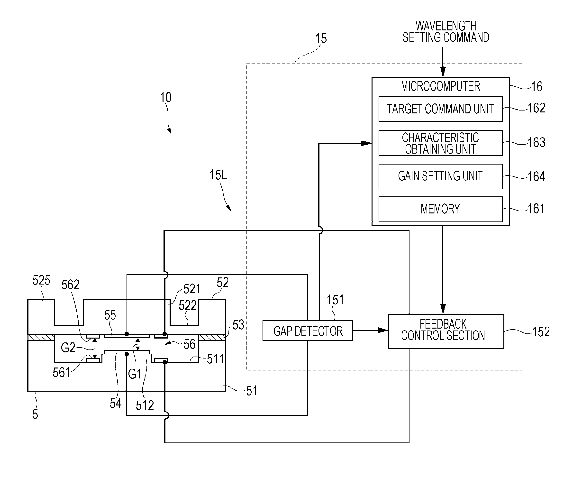
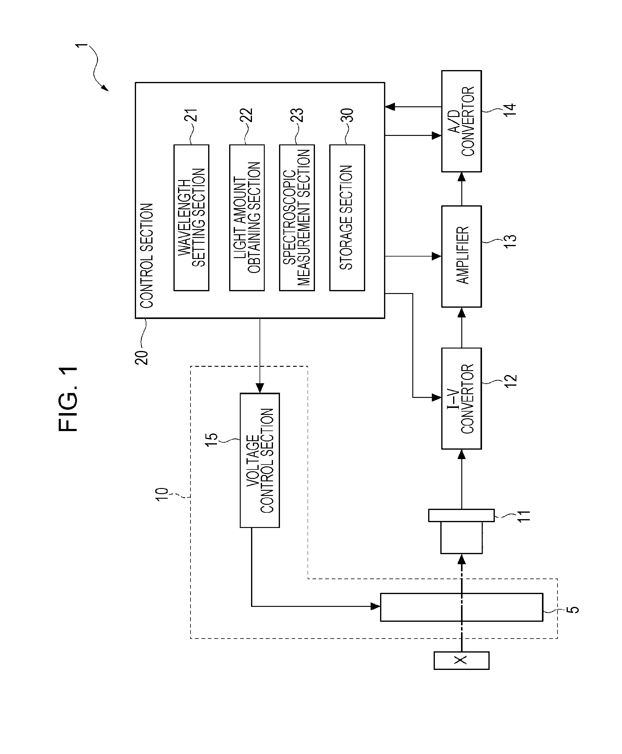
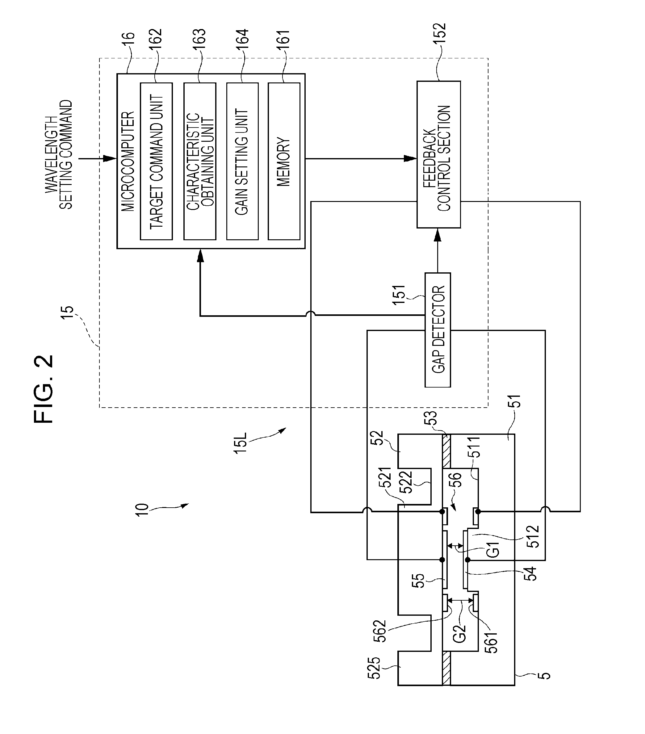
[0049]FIG. 1 is a block diagram illustrating a schematic configuration of a spectroscopic measurement apparatus of a first embodiment according to the invention.

[0050]A spectroscopic measurement apparatus 1 is an electronic apparatus of the invention and is an apparatus that analyzes light intensity of a predetermined wavelength in measurement object light reflected on a measurement object X and measures spectral spectrum. Moreover, in the embodiment, an example in which the measurement object light reflected on the measurement object X is measured is described, but as the measurement object X, for example, if a light emitter such as a liquid crystal display is used, the light emitted from the light emitter may be a light that is measurement object.

[0051]As illustrated in FIG. 1,...

second embodiment

[0135]Next, a second embodiment of the invention will be described with reference to the drawings.

[0136]In the first embodiment described above, in step S2, the characteristic obtaining unit 163 obtains the drive characteristics of the electrostatic actuator 56 from the initial gap dimension of the gap G2. In contrast, the second embodiment is different from the first embodiment described above in that the drive characteristics of the electrostatic actuator 56 are obtained based on a plurality of measuring points.

[0137]In addition, in the following description, the same reference numerals are given to the configurations described above and the description thereof will be omitted or simplified.

[0138]FIG. 7 is a diagram illustrating an obtaining method of drive characteristic data of the second embodiment.

[0139]In the embodiment, a characteristic obtaining unit 163 obtains a plurality of dimensions (measuring points c) of a gap G2 by changing the drive voltage based on the detection s...

third embodiment

[0142]Next, a third embodiment of the invention will be described with reference to the drawings.

[0143]In the first and the second embodiments described above, the optical module 10 that controls the gap G1 between the reflective films 54 and 55 to a desired value by using one electrostatic actuator 56 is exemplified.

[0144]In contrast, in the third embodiment, the electrostatic actuator includes a first actuator and a second actuator capable of respectively being independently driven, and the third embodiment is different from the first and second embodiments in that the dimension of the gap G1 is controlled by the first and second actuators.

[0145]FIG. 8 is a diagram illustrating a schematic configuration of an optical module of a third embodiment. FIG. 9 is a plan view of a variable wavelength interference filter.

Configuration of Variable Wavelength Interference Filter

[0146]A variable wavelength interference filter 5A of the embodiment is different from the first and second embodim...


PUM


Abstract

A spectroscopic measurement apparatus includes an electrostatic actuator that is driven by applying a drive voltage, a gap detector that detects a dimension of a gap, a closed loop system that controls the drive voltage applied to the electrostatic actuator depending on a detection signal from the gap detector, and a gain setting unit that sets a gain in the closed loop system depending on drive characteristics of electrostatic actuator based on the detection signal of the gap detector.

Description

BACKGROUND[0001]1. Technical Field[0002]The present invention relates to an actuator control device, an optical module, an electronic apparatus, and an actuator control method.[0003]2. Related Art[0004]In the related art, a variable wavelength interference filter including a pair of substrates facing each other, reflective films respectively disposed in each substrate and facing each other, and electrodes respectively disposed in each substrate and facing each other is known (for example, JP-A-1-94312).[0005]In the variable wavelength interference filter described in JP-A-1-94312, electrostatic capacitance monitor electrodes facing each other and electrostatic force applying electrodes (electrostatic actuator) facing each other are respectively disposed in each substrate. In such a variable wavelength interference filter, a voltage is applied to the electrostatic actuator by a control circuit and thereby a gap amount (interval dimensions) between reflective films is changed. In addi...

Claims


Application Information

Patent Timeline
IPC IPC(8): G02B26/00H02N1/00G05B6/02
CPCG02B26/001H02N1/006G05B6/02G01J3/26G02B26/02G02B26/00H02N1/00G05B6/00
Inventor HIROKUBO, NOZOMU
Owner SEIKO EPSON CORP
Why Eureka
Try Eureka