Aligning source-grating-to-phase-grating distance for multiple order phase tuning in differential phase contrast imaging

Active Publication Date: 2015-08-06
KONINKLJIJKE PHILIPS NV
View PDF1 Cites 14 Cited by
  • Summary
  • Abstract
  • Description
  • Claims
  • Application Information

AI Technical Summary

Benefits of technology

[0003]Thus, there may be a need to provide a reduction for the pre-tuning and adjustment re

Problems solved by technology

However, it has been shown that tuning and stabilizing such an interferometer in hos

Method used


Image

  • Aligning source-grating-to-phase-grating distance for multiple order phase tuning in differential phase contrast imaging
  • Aligning source-grating-to-phase-grating distance for multiple order phase tuning in differential phase contrast imaging
  • Aligning source-grating-to-phase-grating distance for multiple order phase tuning in differential phase contrast imaging

Examples


Example

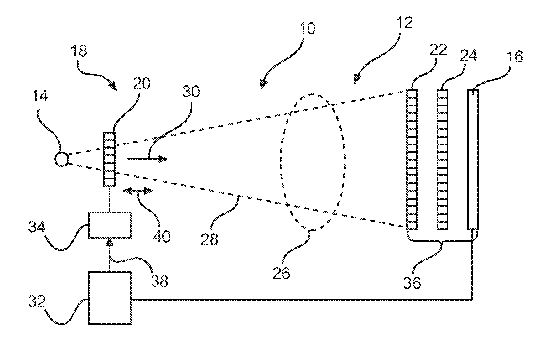
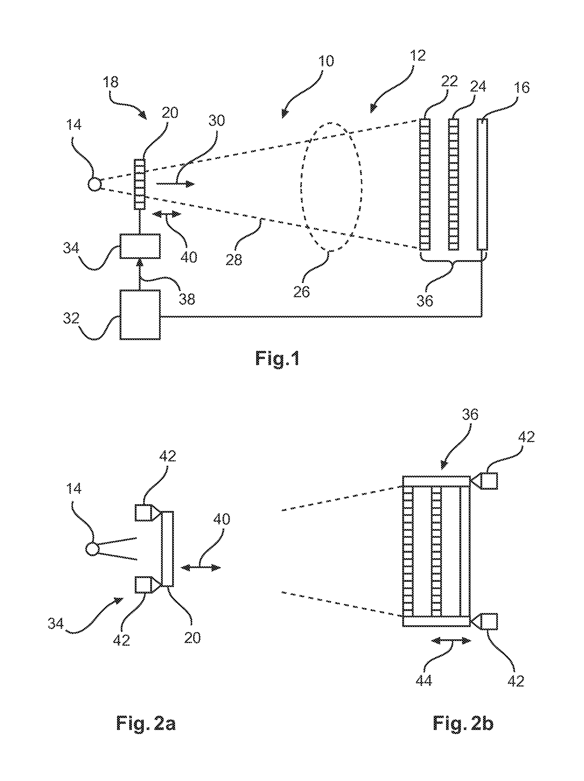
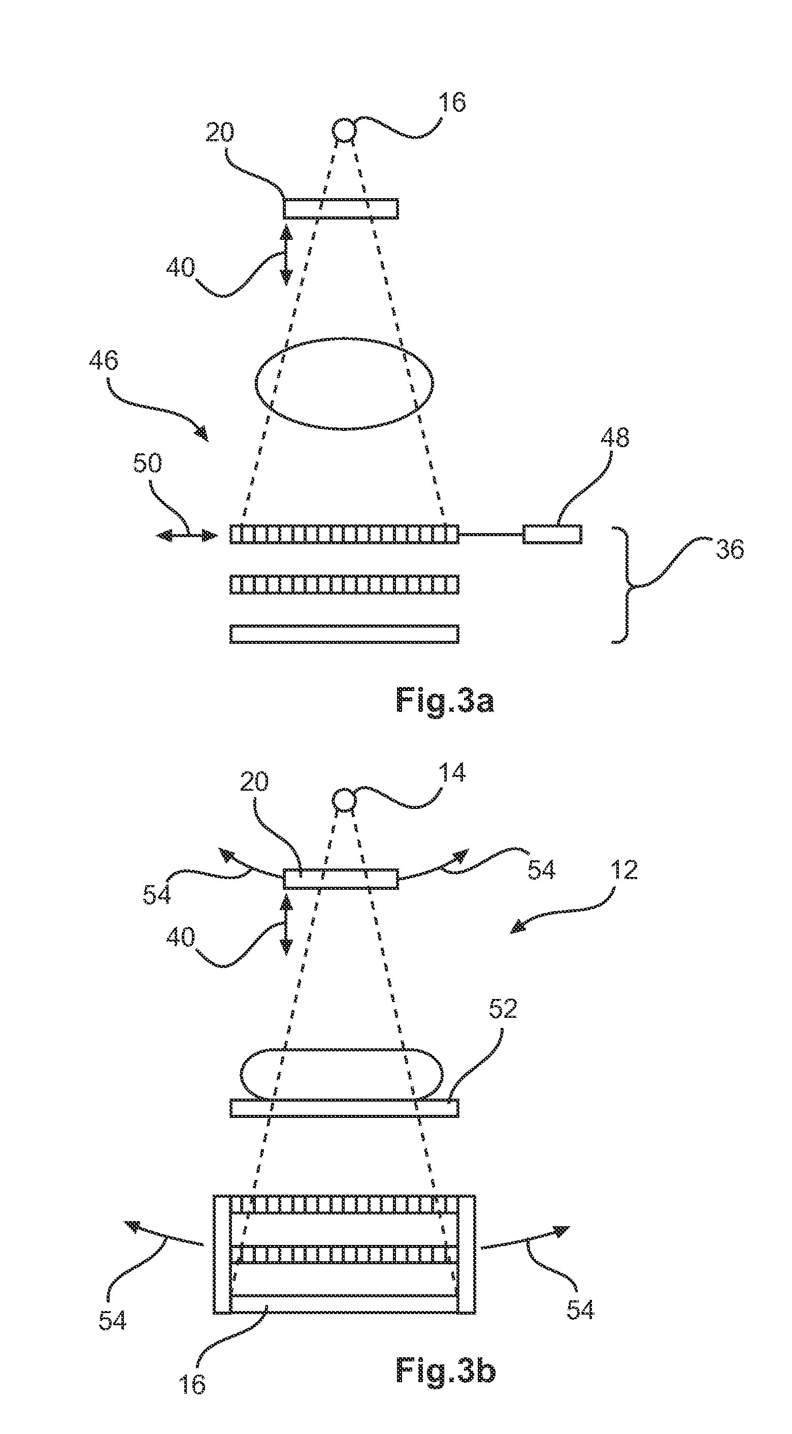
[0025]FIG. 1 shows an X-ray imaging system 10 for differential phase contrast imaging, comprising a differential phase contrast setup 12 with an X-ray source 14 and an X-ray detector 16. Further, a grating arrangement 18 is provided, comprising a source grating 20, a phase grating 22, and an analyser grating 24. The source grating is arranged between the X-ray source and the phase grating, and the analyser grating is arranged between the phase grating and the detector. Further, a moving arrangement for a relative movement between an object under examination and at least one of the gratings is provided (not further shown). A dotted oval structure 26 indicates an object, and an X-ray beam 28 in a fan-shaped formation is also indicated, together with an X-ray projecting direction 30. Further, a processing unit 32 is provided, and a translation arrangement 34 for translating the source grating. The phase grating, the analyser grating, and the detector are provided as a rigid interferome...


PUM


Abstract

The present invention relates handling misalignment in an X-ray imaging system for differential phase contrast imaging. In order to provide a reduction for the pretuning and adjustment requirements for manufacture and maintenance in a differential phase contrast imaging system, an X-ray imaging system (10) for differential phase contrast imaging, is provided that comprises a differential phase contrast setup (12) with an X-ray source (14) and an X-ray detector (16), a grating arrangement (18) comprising a source grating (20), a phase grating (22) and an analyser grating (24), wherein the source grating is arranged between the X-ray source and the phase grating, and the analyser grating is arranged between the phase grating and the detector. Further, a moving arrangement for a relative movement between an object under examination and at least one of the gratings is provided, as well as a processing unit (32), and a translation arrangement (34) for translating the source grating. The phase grating, the analyser grating and the detector are provided as a rigid interferometer unit (36), in which the phase grating and the analyser grating are mounted in parallel to each other. The source grating is misaligned in respect to the interferometer unit such that moiré fringes are detectable in the plane of the detector. The processing unit is configured to detect moiré patterns in signals provided by the detector upon X-ray radiation. The processing unit is further configured to compute a translation signal (38) for translating the source grating for achieving a predetermined moiré pattern. The translation arrangement is configured to adjust the positioning of the source grating at least in the X-ray projection direction (30), based on the value of the translation signal.

Description

FIELD OF THE INVENTION[0001]The present invention relates to an X-ray imaging system for differential phase contrast imaging, to a method for handling misalignment in an X-ray imaging system for differential phase contrast imaging, to a computer program element and to a computer readable medium.BACKGROUND OF THE INVENTION[0002]Differential phase contrast imaging (DPCI) is an emerging technology that has a potential to improve the diagnostic value of X-ray imaging. For example, one application of this technology is mammography. In a DPCI system, a setup is used with three gratings between the X-ray source and the detector. For image acquisition, several X-ray images at different relative positions of two of the gratings are provided. Since the gratings have pitches in the order of a few micrometres only, there are rather tight requirements on the accuracy of the stepping device that performs the relative movement of the gratings, and also for alignment of the system. For larger objec...

Claims


Application Information

Patent Timeline
IPC IPC(8): A61B6/00
CPCG01N23/20025G01N2223/643A61B6/484G01N23/20075A61B6/587A61B6/588A61B6/589A61B6/582
Inventor MARTENS, GERHARDDAERR, HEINERISTEL, THOMAS DETLEFROESSL, EWALDVAN STEVENDAAL, UDO
Owner KONINKLJIJKE PHILIPS NV
Why Eureka
Try Eureka