Method and apparatus for generating self rotating fluid jet

a self-rotating, fluid-jet technology, applied in mechanical equipment, cleaning using liquids, manufacturing tools, etc., can solve the problems of high-pressure high-speed rotary joints that are expensive and high-maintenance components, and the complete nozzle system of this type is rather bulky and complicated, and the nozzle shakes often excessively, so as to increase the surface-coverage capacity, the effect of greater fluid-jet spinning and greater capabilities

Active Publication Date: 2015-08-06
YIE GENE G
View PDF4 Cites 18 Cited by
  • Summary
  • Abstract
  • Description
  • Claims
  • Application Information

AI Technical Summary

Benefits of technology

[0008]One object of this invention is to provide a pivotally rotating jet (PRJ) fluid jet nozzle that provides greater fluid jet spinning or rotating speed to increase the surface-coverage capability, rotating fluid jets of greater capabilities by using high-quality orifices, improved fluid sealing in the nozzle and thus improved pressure capabilities, improved tool inventory and field operation ease, and a nozzle with greater overall capability and versatility.
[0009]The pivotally rotating nozzle of this invention follows one principle of generating spinning

Problems solved by technology

As a result, high-pressure high-speed rotary joints are costly and are high-maintenance components, and are avoided if possible.
As a result, a complete nozzle system of this type is rather bulky and complicated.
In applications, the nozzle often shakes excessively due to the orbital jet motion and attempts have been made to isolate such

Method used


Image

  • Method and apparatus for generating self rotating fluid jet
  • Method and apparatus for generating self rotating fluid jet
  • Method and apparatus for generating self rotating fluid jet

Examples


example i

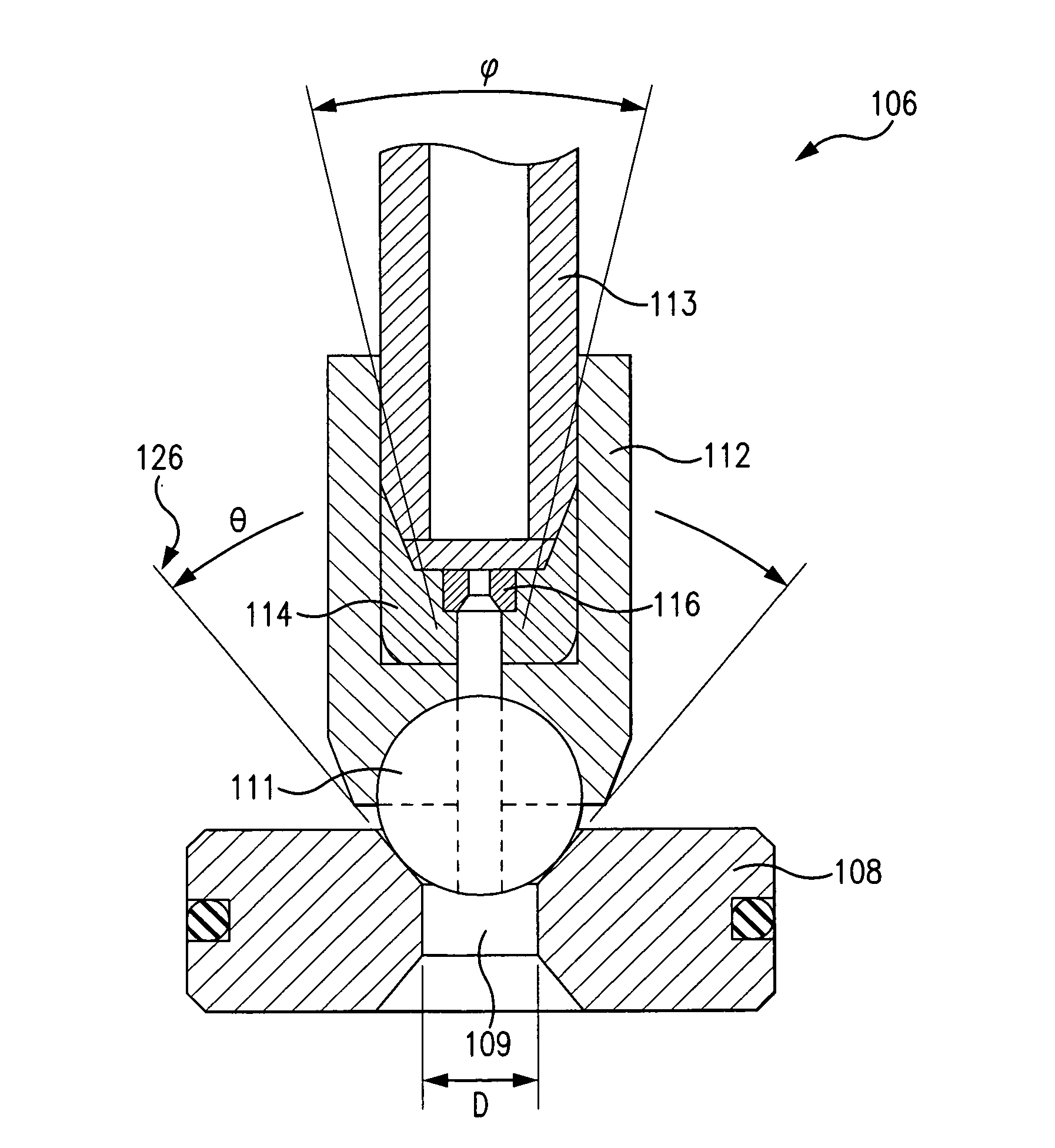
[0056]A pivotally rotating jet nozzle assembly was constructed according to nozzle assembly 100 of this invention. The nozzle body is made of hardened stainless steel and is 1.4 inches wide and 2.4 inches tall having a cylindrical cavity of 0.75 inches in diameter and 2.10 inches in depth. A mating nozzle cap was also made of hardened stainless steel and was attached to the nozzle body by 1-1 / 8-12 threads. A rotor assembly was assembled using a 5 mm diameter tungsten-carbide ball hard soldered to a stainless-steel ball anchor of 0.31 inches in diameter and 0.5 inches in length. A 0.25-inch-diameter stainless-steel tube was threaded into this ball anchor and butted against an orifice plug having a jewel orifice of selected size. The overall length of this assembled rotor assembly was 2.0 inches. The rotor ball has a 0.079-inch-diameter center hole and the orifice plug had a jewel orifice of 0.040 to 0.048 inches. The nozzle seat was made of hardened stainless-steel and was 0.500 inch...

example ii

[0057]A relatively small rotary joint was constructed according to rotary joint 800 of this invention. The joint body was 0.375 inches in outside diameter, 2.0 inches in length and had a cavity of 0.281 inches in diameter housing a rotor assembly made with a 0.250-inch-diameter hardened stainless-steel ball having a 0.156-inch-diameter center hole accommodating a rotor tube assembly made of stainless steel. The rotor tube assembly had a body of 0.250 inches in diameter and a 0.156-inch-diameter tube extended to the exterior of the nozzle body. The rotor tube body had a short center post of 0.125 inches in diameter positioned in a hole made on the closed end of the joint cavity that also served as the fluid inlet. The total length of the rotor assembly was 2.0 inches and had a through center fluid passage of 0.079 inches in diameter. The exposed rotor tube end was threaded and fitted with a relatively small nozzle having two 0.035-inch-diameter orifices offset from the center or cent...

example iii

[0058]A nozzle assembly according to nozzle assembly 1500 of this invention was constructed. The nozzle body was 0.375 inches in outside diameter, 2.0 inches in length, and had a cavity of 0.272 inches in diameter and was made of hardened stainless steel. The orifice cone was made of stainless steel having 0.270 inches in outside diameter, 90-degree convex and concave faces, and a center fluid passage of 0.078 inches in diameter. There were two jewel orifices mounted on opposite sides of the concave face of the orifice cone at 45 degrees to the center line and offset by 20 degrees to force or generate counterclockwise rotation. The orifices were made of sapphire and had a center hole of 0.023 inches in diameter. The nozzle head was made of hardened stainless steel and had three 0.023-inch-diameter jewel orifices made of sapphire as well. These three orifices were positioned in a triangle and were all facing forward but at different angles. These angles were determined by examining t...


PUM

PropertyMeasurementUnit
Forceaaaaaaaaaa
Angleaaaaaaaaaa
Speedaaaaaaaaaa

Abstract

A nozzle assembly for generating fluid jets, such as self-spinning fluid jets. A nozzle body includes a cylindrical nozzle cavity, an inlet, an outlet, and a tubular nozzle rotor assembly positioned with respect to the nozzle cavity. The nozzle rotor assembly can have a ball end and a tubular end and a central fluid passage routed through the nozzle rotor assembly. A fluid swirl enhancer forms communication with the inlet. A replaceable nozzle seat forms communication with the ball end of the nozzle rotor assembly and with the outlet. The ball end of the nozzle rotor assembly pivots, oscillates and rotates against the nozzle seat when pressurized fluid flows through the nozzle assembly.

Description

BACKGROUND OF THE INVENTION[0001]Fluid jets, such as water jets, generated at relatively high static pressures with a suitable pump and nozzle travel in or through air at a relatively high speed. Such high-speed water-jets, often greater than sonic velocity, are conventionally used in many industrial and commercial processes, such as surface cleaning and preparation, coating removal, ship-hull barnacle removal, and concrete scarification and demolition. In such applications, the productivity of the process is measured by how well and how fast the water-jets are applied to the surface. To maximize the surface coverage of the water-jets, the water-jet nozzle is moved over the surface by hand with a hand tool or by an automated or manual mechanical system to provide the desired nozzle movement. The water jet nozzle or nozzles are often rotated and then moved linearly on the surface. To provide the rotation, the nozzles are attached to a suitable swivel or rotary joint that allows press...

Claims


Application Information

Patent Timeline
IPC IPC(8): B05B3/04F16L27/02B24C7/00B05B1/34B24C3/12
CPCB05B3/0418B05B1/341F16L27/023B24C7/0023B24C3/12B05B1/14B05B3/0463B05B3/06B08B3/02B05B13/0636B08B9/0433B08B9/0495B24C1/045B24C5/04B26F3/004
Inventor YIE, GENE G.
Owner YIE GENE G
Why Eureka
Try Eureka