Surge protection circuit

a protection circuit and surge protection technology, applied in the direction of circuit arrangements, emergency protection arrangements for limiting excess voltage/current, and arrangements responsive to excess voltage, can solve the problems of easy damage to elements, shortened service life of the whole led driving power supply, and most common damage to lightning, so as to prolong the service life of the related electronic protection and reduce residual voltage

Inactive Publication Date: 2015-08-06
TONLIER ENERGY TECHBEIJINGCO
View PDF0 Cites 8 Cited by
  • Summary
  • Abstract
  • Description
  • Claims
  • Application Information

AI Technical Summary

Benefits of technology

[0013]In the present invention, a DM inductor is connected in a surge protection circuit, so as to fully utilize characteristics of the DM inductor; the EMI is effectively suppressed, and the damage caused to the surge protection element by overvoltage and overcurrent shocks may also be effectively avoided, so as to reduce residual voltage and prolong the service life of a related electronic protect.

Problems solved by technology

However, the most common damage of the lightning is not caused by direct lightning, but is caused by an inductive current surge in the driving power supply when the lightning occurs.
However, in an actual application, the surge protection circuit is often damaged because of multiple surge shocks, so that the service life of the whole LED driving power supply is shortened.
In an actual application of a surge protection circuit, a surge protection element is generally close to an input end of AC, and a piezoresistor and a protected circuit are struck by multiple surges, so that the elements are easily damaged, and the service life of a related electronic product is significantly shortened.

Method used


Image

  • Surge protection circuit
  • Surge protection circuit
  • Surge protection circuit

Examples


first embodiment

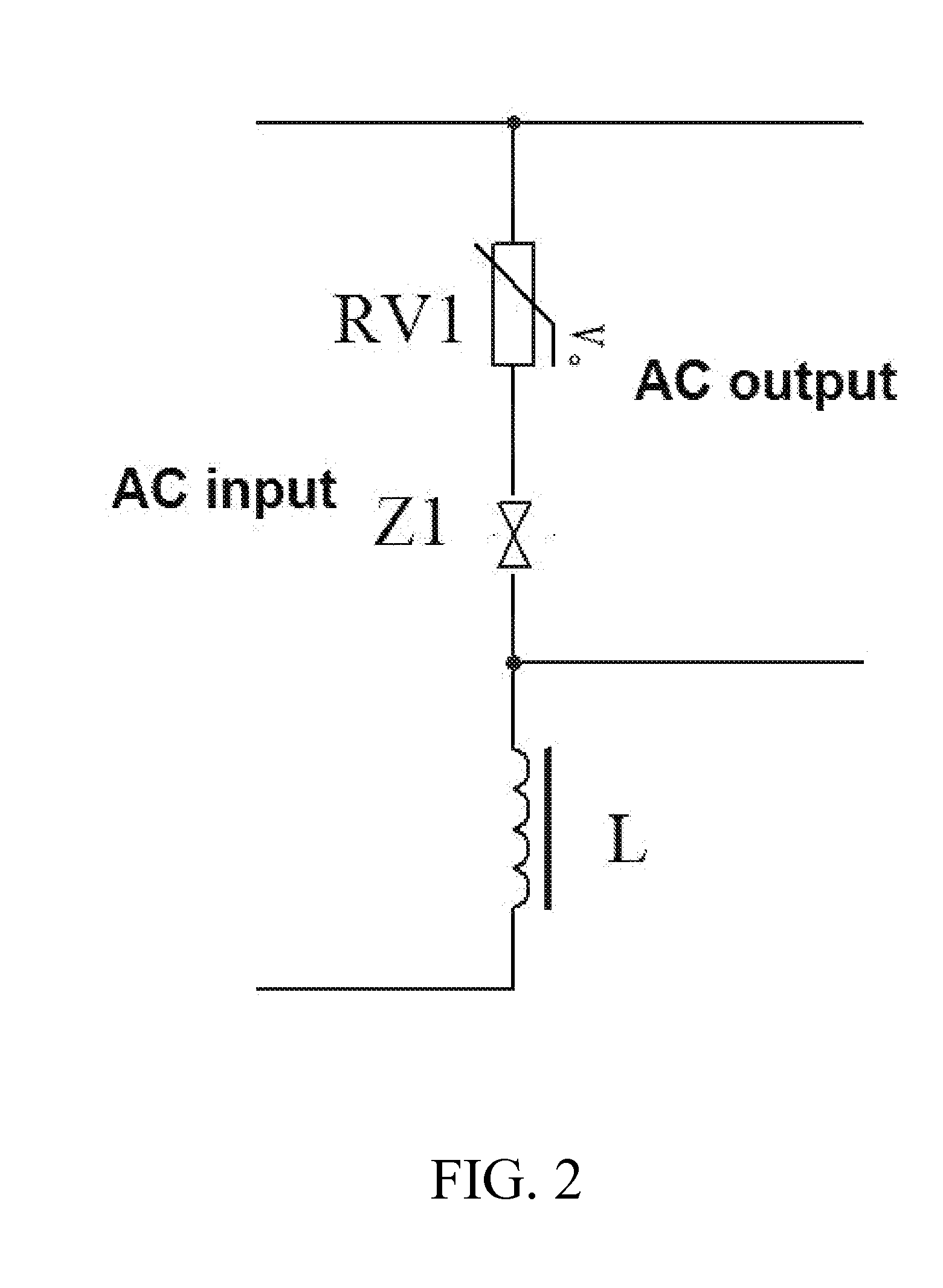
[0024]The surge protection circuit provided by the present invention includes a piezoresistor, a discharge tube and a DM inductor. It should be noted that, the discharge tube may also be replaced by a short-circuit wire. The discharge tube preferably adopts a gas discharge tube. Referring to FIG. 2, one of alternating current (AC) input ends is serially connected to the DM inductor L. a circuit formed by serially connecting the piezoresistor RV1 and the gas discharge tube Z1 is connected in parallel between AC output ends. When the piezoresistor is applied for protection of an AC power supply system, because of a large parasitic capacitance, leakage current often occurs in a normal operation state. The leakage current often affects normal operation of another circuit. After the piezoresistor is serially connected to the discharge tube, because the parasitic capacitance of the discharge tube is very small, the total capacitance of the whole series circuit is reduced. The gas discharg...

second embodiment

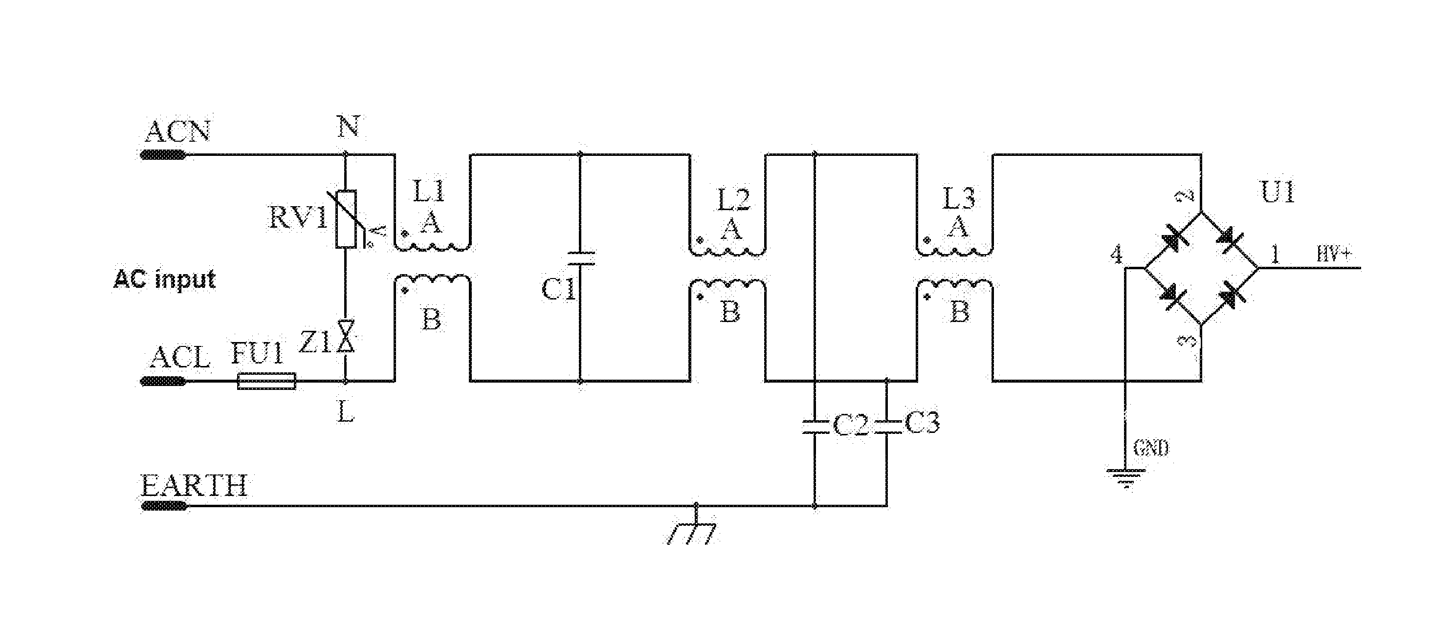
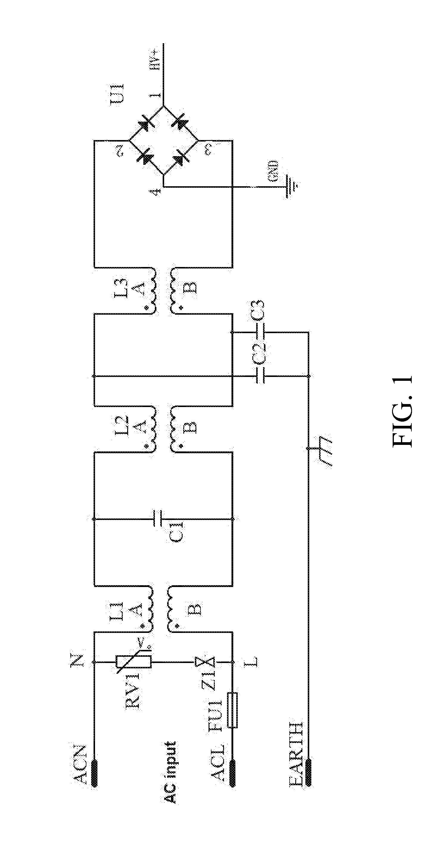
[0026]A surge protection circuit in this embodiment is implemented in combination with an electromagnetic interference (EMI) filter circuit. In FIG. 1, a conventional switching power supply circuit includes a surge protection circuit, an EMI filter circuit and a rectifier circuit. The surge protection circuit is connected in parallel between a neutral wire ACN and a live wire ACL. After being connected in parallel to the surge protection circuit, the neutral wire ACN and the live wire ACL are then connected to the EMI filter circuit. The EMI filter circuit is connected to the rectifier circuit. When a surge occurs, the gas discharge tube is broken down and discharges to be conducted, and the piezoresistor clamps a voltage between the neutral wire and the live wire to ensure subsequent normal working of the circuit. However, the surge protection element may be damaged after multiple shocks of overvoltage and overcurrent, so that the service life of the whole switching power supply is...

third embodiment

[0031]Referring to FIG. 6, this embodiment is a variation based on the second embodiment, where connection manners of an electromagnetic interference (EMI) filter circuit and a rectifier circuit may be obtained with reference to the second embodiment. A difference between this embodiment and the second embodiment lies in connection positions of a piezoresistor, a gas discharge tube, and the EMI filter circuit. In this embodiment, only half inductors of two stages of common mode (CM) inductors are used as a differential mode (DM) inductor. One end N of a series circuit formed by the gas discharge tube and the piezoresistor is connected to an output end of a first-stage CM inductor L1A, and the other end L′ is connected to an output end of a third-stage CM inductor L3B.

[0032]FIG. 7 is a circuit diagram after connection sequences of the piezoresistor and the gas discharge tube are exchanged, and has working principles the same as those in FIG. 6. Hereinafter, working principles of the ...


PUM


Abstract

The present invention discloses a surge protection circuit. The surge protection circuit is formed by serially connecting a piezoresistor, a discharge tube and a differential mode (DM) inductor. The present invention fully utilizes characteristics of the DM inductor, effectively suppresses electromagnetic interference, and can also effectively avoid damage caused to a surge protection element by over-voltage and over-current shocks, reduce a residual voltage, and prolong the service life of a related electronic product.

Description

BACKGROUND[0001]1. Technical Field[0002]The present invention relates to a surge protection circuit, and more particularly, to a surge protection circuit implemented based on a differential mode (DM) inductor, and a light-emitting diode (LED) driving power supply using the circuit.[0003]2. Related Art[0004]Lightning discharge is a common gas discharge phenomenon, which can generate a high-frequency peak surge voltage within an extremely short period of time, and significantly influences the reliability of a switching power supply, especially an LED driving power supply, connected to an alternating current (AC) network. However, the most common damage of the lightning is not caused by direct lightning, but is caused by an inductive current surge in the driving power supply when the lightning occurs. With the high-speed development of the LED lighting technology, there are increasingly high requirements on performance of the LED driving power supply; however, due to highly integration...

Claims


Application Information

Patent Timeline
Patent Type & Authority Applications(United States)
IPC IPC(8): H02H3/08H05B33/08H05K9/00H05B44/00
CPCH02H9/041H02H9/042H05B33/0815H02H3/08H05K9/00H02H9/06H02H9/043H05B45/3725Y02B20/30
Inventor WANG, ZHENCHEN, YONGHUAN
Owner TONLIER ENERGY TECHBEIJINGCO
Why Eureka
Try Eureka