Vibration suppression structure for front-end module

a front-end module and vibration suppression technology, applied in the direction of machines/engines, electric propulsion mounting, liquid fuel engines, etc., can solve the problems of pulsation sound and vibration propagation, insufficient suppression of vehicle parts, and compromise of vibration suppression characteristics

Active Publication Date: 2015-08-13
NISSAN MOTOR CO LTD
View PDF14 Cites 6 Cited by
  • Summary
  • Abstract
  • Description
  • Claims
  • Application Information

AI Technical Summary

Benefits of technology

[0017]On the other hand, when the second in-vehicle part vibrates as a part at a frequency in the second frequency band (high frequency band), the vibration from the second in-vehicle part is damped by the second mount member along with the heat exchanger support frame before being transmitted to the vehicle body, whereby pulsation sound and vibration propagated from the vehicle body into the vehicle compartment can be suppressed to a small amount. In this configuration, the second mount member, via which the heat exchanger support frame is supported by the vehicle body, does not need to damp vibration at a frequency in the first frequency band (low frequency band) and can therefore be formed of a hard member having a high spring constant, whereby the rigidity with which the heat exchanger support frame is supported by the vehicle body is not lowered.
[0018]As described above, the vibration suppression structure that damps vibration of a part at a frequency in the first frequency band (low frequency band) and the vibration suppression structure that damps vibration of a part at a frequency in the second frequency band (high frequency band) are configured to differ from each other. As a result, pulsation sound / vibration propagated from the plurality of in-vehicle parts incorporated in the vehicle front section via the vehicle body into the vehicle compartment can be suppressed without a decrease in the rigidity with which the in-vehicle parts are supported by the vehicle body.

Problems solved by technology

However, even when the plurality of in-vehicle parts are fixed to the radiator core support and the radiator core support is elastically supported by a vehicle body, there are still in-vehicle parts that cannot be sufficiently suppressed in terms of vibration because the plurality of in-vehicle parts have different vibration frequency bands within which they vibrate, undesirably resulting in pulsation sound and vibration propagated from these in-vehicle parts into a vehicle compartment.
For example, tuning a mount member via which the radiator core support is elastically supported by the vehicle body in such a way that vibration in high frequency bands is damped compromises vibration suppression characteristics of in-vehicle parts that vibrate in low frequency bands.
Conversely, tuning the mount member, via which the radiator core support is elastically supported by the vehicle body, in such a way that vibration in the low frequency bands is damped lowers supporting rigidity of the radiator core support, possibly resulting in newly produced vibration due to external excitation, for example, from a road surface.

Method used


Image

  • Vibration suppression structure for front-end module
  • Vibration suppression structure for front-end module
  • Vibration suppression structure for front-end module

Examples


embodiment 1

[0029]First, the configuration will be described.

[0030]The configuration of the vibration suppression structure of the front-end module in Embodiment 1 is divided into “General configuration of the front-end module incorporated in a vehicle,”“Overall system configuration including in-vehicle parts in the front-end module,” and “Detailed configuration of the vibration suppression structure of the front-end module,” and each of the configurations will be described below.

[0031]General Configuration of Front-End Module Incorporated in Vehicle

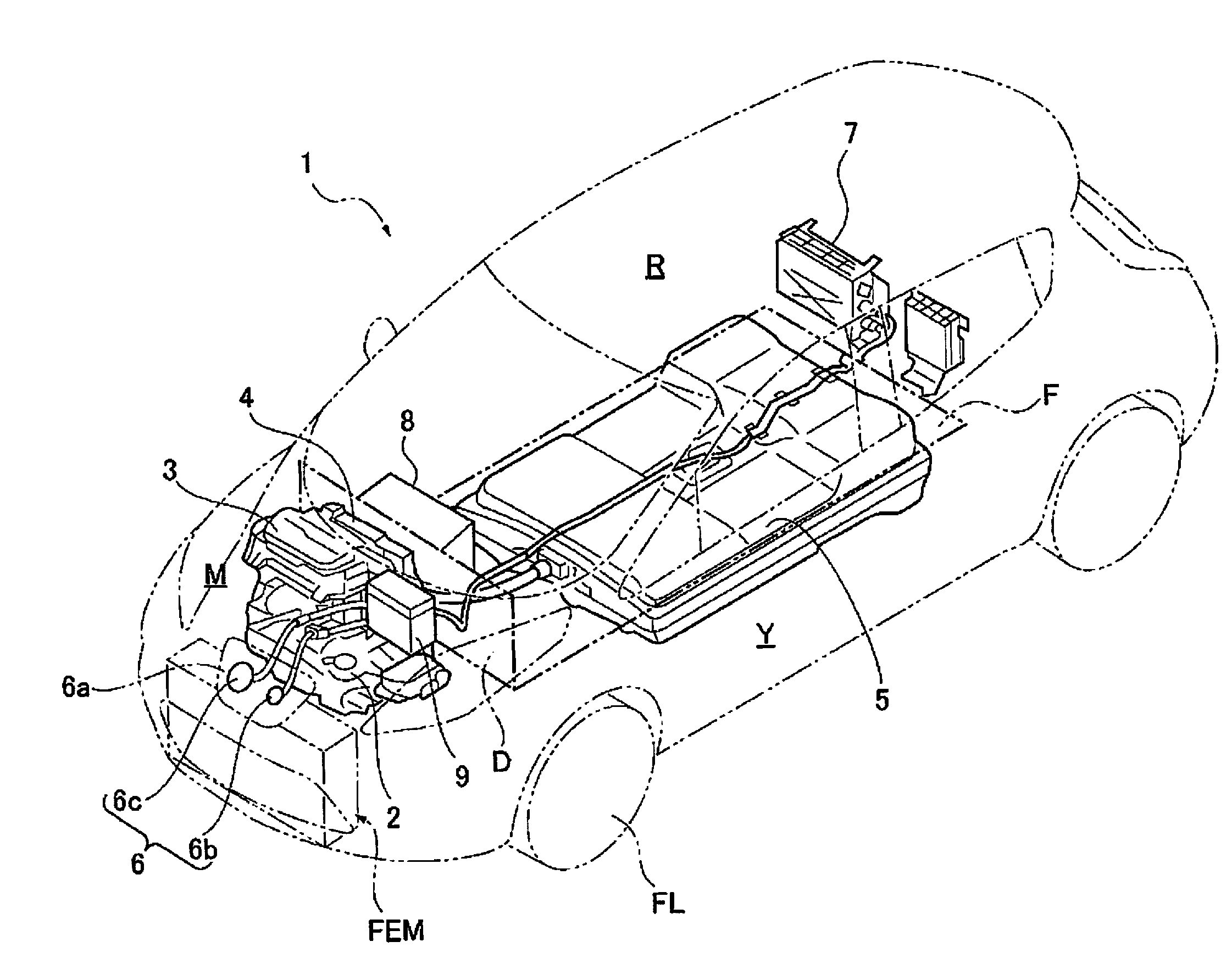
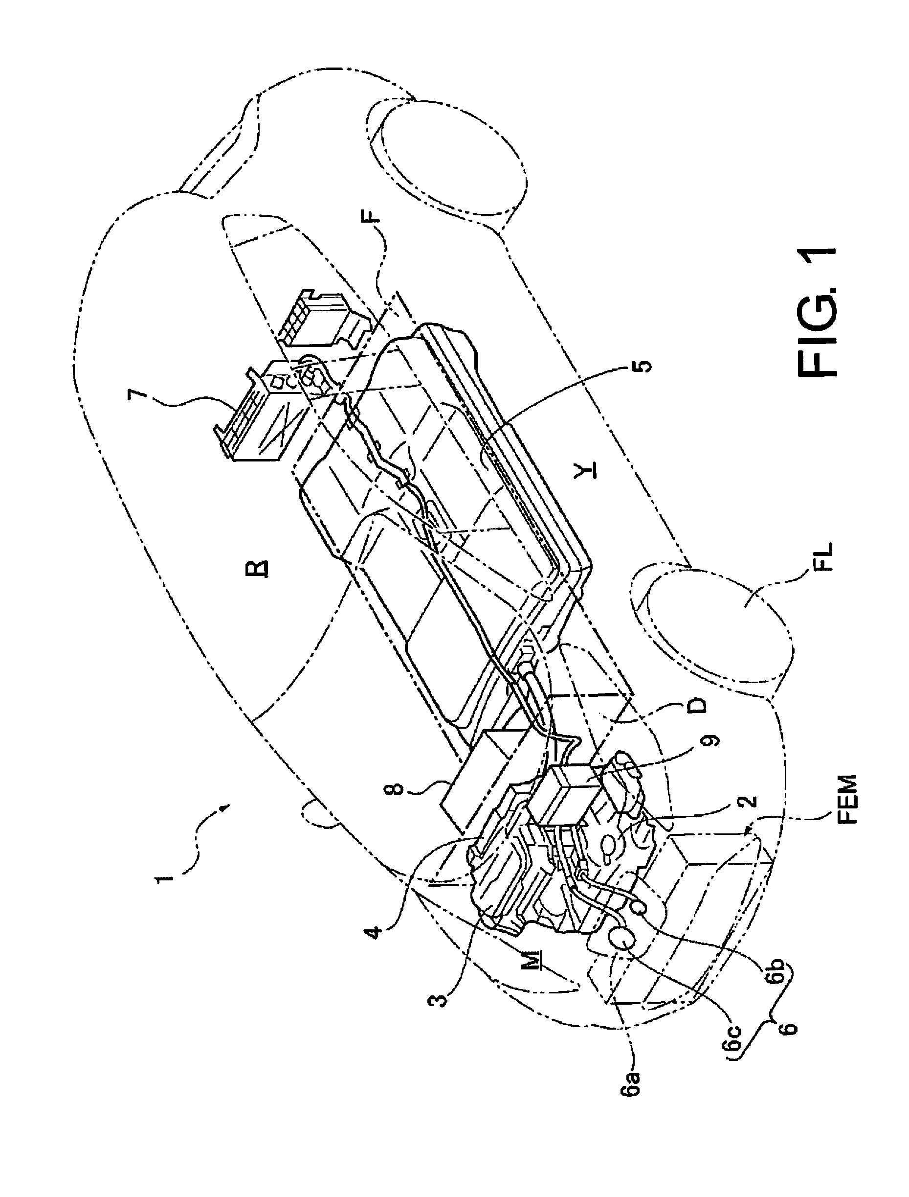
[0032]FIG. 1 shows a schematic configuration of a sedan-type electric automobile in which a front-end module FEM according to Embodiment 1 is incorporated. A general configuration of the front-end module FEM incorporated in the vehicle is described below with reference to FIG. 1.

[0033]An electric automobile 1 in which the front-end module FEM according to Embodiment 1 is incorporated includes a driving motor 2, a driving motor inverter 3, a DC / DC ju...


PUM


Abstract

A front-end module (FEM) having in-vehicle parts incorporated in a vehicle front section are aggregated and assembled to a heat exchanger support frame, the plurality of in-vehicle parts are classified into first in-vehicle parts, which vibrate at frequencies in a first frequency band, and a second in-vehicle part, which vibrates at a frequency in a second frequency band having a frequency range higher than the frequency range in the first frequency band. The first in-vehicle parts are elastically supported by the heat exchanger support frame via first mount members. The second in-vehicle part is rigidly fixed to the heat exchanger support frame. The heat exchanger support frame is elastically supported by a vehicle body via second mount members.

Description

CROSS-REFERENCE TO RELATED APPLICATIONS[0001]This application is a U.S. National stage application of International Application No. PCT / JP2013 / 072036, filed Aug. 16, 2013 which claims priority to Japanese Patent Application No. 2012-202473 filed in Japan on Sep. 14, 2012, the contents of each of which are hereby incorporated herein by reference.BACKGROUND[0002]1. Field of the Invention[0003]The present invention relates to a vibration suppression structure for a front-end module in which a plurality of in-vehicle parts incorporated in a vehicle front section are aggregated and assembled to a heat exchanger support frame.[0004]2. Background Information[0005]There is a known cooling part support apparatus for a vehicle of related art in which a radiator core support that is a substantially rectangular frame member is disposed in a front section of a vehicle body and a radiator is supported in a space surrounded by the radiator core support (see Japanese Laid-Open Patent Application No...

Claims


Application Information

Patent Timeline
Patent Type & Authority Applications(United States)
IPC IPC(8): B60K11/04F16F15/04
CPCF16F15/04B60K11/04B60H1/3227B60K2001/001B60K2001/003B60K2001/006B60K2001/0438B62D25/084F04D29/522F04D29/668B60H1/3229
Inventor MATANO, SHINICHIONISHI, MASAHIROTAKAHASHI, MIWAKO
Owner NISSAN MOTOR CO LTD
Why Eureka
Try Eureka