Automatic V-belt transmission

Active Publication Date: 2006-05-02
KAWASAKI MOTORS LTD
View PDF14 Cites 15 Cited by
  • Summary
  • Abstract
  • Description
  • Claims
  • Application Information

AI Technical Summary

Benefits of technology

[0023]In the mechanism, the “position of maximum reduction in speed” is such a position in which a reduction ratio in rotational speed between the drive pulley and the driven pulley is the maximum in a state in which there is no substantial slippage between the drive pulley and the V-belt engaging with the drive pulley. According to the mechanism, not only the squeaking noise of the clutch caused by the relative sliding between the V-belt and the sheave as aforementioned, but also the judder phenomenon caused by the twisting vibration of the V-belt, are both suppressed. In addition, when the V-belt becomes positioned on a side of higher spe

Problems solved by technology

As a result, the self-induced vibration triggers the occurrence of so-called “belt squeaking noise (or belt squeaking soun

Method used


Image

  • Automatic V-belt transmission
  • Automatic V-belt transmission
  • Automatic V-belt transmission

Examples


Embodiment Construction

[0037]Before a description of the preferred embodiment of the present invention proceeds, it is to be noted that like or corresponding parts are designated by like reference numerals throughout the accompanying drawings.

[0038]With reference to FIGS. 1 through 9, the description is made below upon an automatic V-belt transmission, applied to a four-wheeled all-terrain vehicle as one example, according to a preferred embodiment of the present invention and to its modifications.

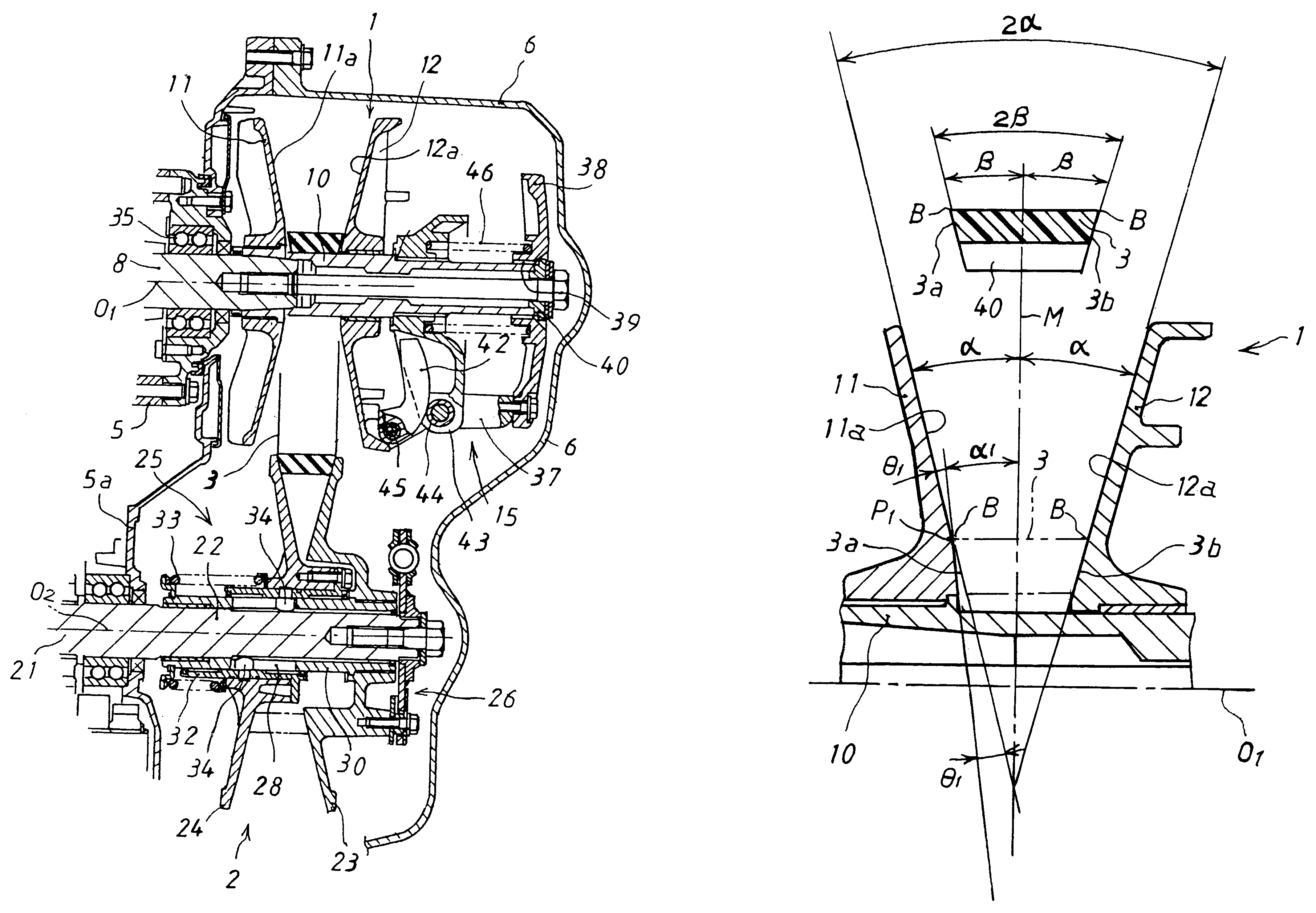
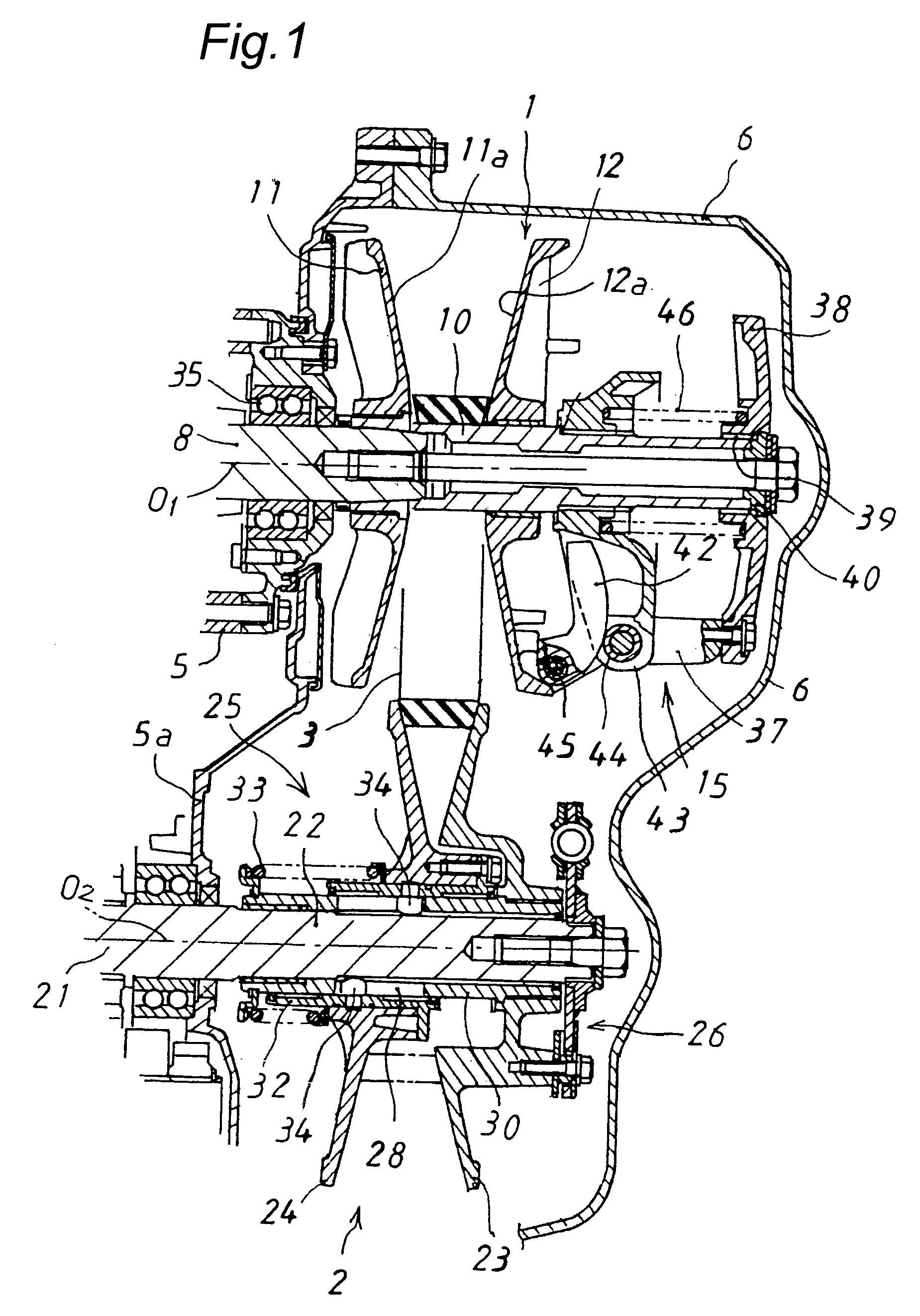
[0039]That is, as shown in FIG. 1 which is a longitudinally sectional view of the automatic V-belt transmission, the transmission has a drive pulley 1, a driven pulley 2, and a V-belt 3 which extends over both of the pulleys 1 and 2. The transmission is housed inside a belt converter cover 6 which is mounted on the right side of a crankcase 5. The drive pulley 1 has a drive shaft 10 which is connected to a crankshaft 8 of an engine, a fixed sheave 11 which is radially fixed to the drive shaft 10, a movable sheav...


PUM


Abstract

A V-belt type of automatic transmitting mechanism includes a drive pulley and a V-belt, and the drive pulley includes a fixed sheave which is fixed to a drive shaft and a movable sheave which is movable in a direction of the drive shaft. When the drive shaft rotates at a higher speed, the movable sheave is moved towards the fixed sheave so that the radius of engagement between each of the sheaves and the V-belt increases. The conical pressure surface of the movable sheave is formed so that an inclined angle thereof is uniform from its radially inner peripheral part to its radially outer peripheral part. Meanwhile, the conical pressure surface of the fixed sheave is formed so that an inclined angle of its radially inner peripheral part is smaller than that of its radially outer peripheral part.

Description

BACKGROUND OF THE INVENTION[0001]1. Field of the Invention[0002]The present invention relates to an automatic V-belt transmission which is suitable for vehicles such as four-wheeled all-terrain vehicles and two-wheeled vehicles.[0003]2. Description of the Related Art[0004]Conventionally, there has been provided an automatic V-belt transmission which has a belt clutch function from a view point of enhancing operability of a vehicle. In the mechanism, while an engine mounted on the vehicle is idling, the belt clutch is being disengaged so as not to cause any excessive creep phenomenon to the vehicle.[0005]FIG. 10 shows a drive pulley 1 for the conventional automatic V-belt transmission having the belt clutch function. The drive pulley 1 has a drive shaft 10 connected to a crankshaft 8 of the engine, a fixed sheave 11 which is fixed to the drive shaft 10, a movable sheave 12 which can move in a direction of the drive shaft axis O1, a flyweight type of propulsion generating mechanism 15...

Claims


Application Information

Patent Timeline
IPC IPC(8): F16H55/56F16H9/12F16H9/18F16H61/662
CPCF16H55/563F16H9/125
Inventor TAKAGI, IZUMI
Owner KAWASAKI MOTORS LTD
Why Eureka
Try Eureka