Softening apparatus

a technology of softening apparatus and softening chamber, which is applied in the direction of moving filter element filter, filtration separation, separation process, etc., can solve the problems of not fundamentally removing a hardness component, affecting the cleaning performance, and affecting the cleaning effect, etc., to achieve convenient and inexpensive effects

a technology of softening apparatus and softening chamber, which is applied in the direction of moving filter element filter, filtration separation, separation process, etc., can solve the problems of not fundamentally removing a hardness component, affecting the cleaning performance, and affecting the cleaning effect, etc., to achieve convenient and inexpensive effects

US20150225260A1Active Publication Date: 2015-08-13SAMSUNG ELECTRONICS CO LTD

Image

  • Softening apparatus
  • Softening apparatus
  • Softening apparatus

Examples


Embodiment Construction

[0039]Reference will now be made in detail to the embodiments of the present disclosure, examples of which are illustrated in the accompanying drawings, wherein like reference numerals refer to like elements throughout.

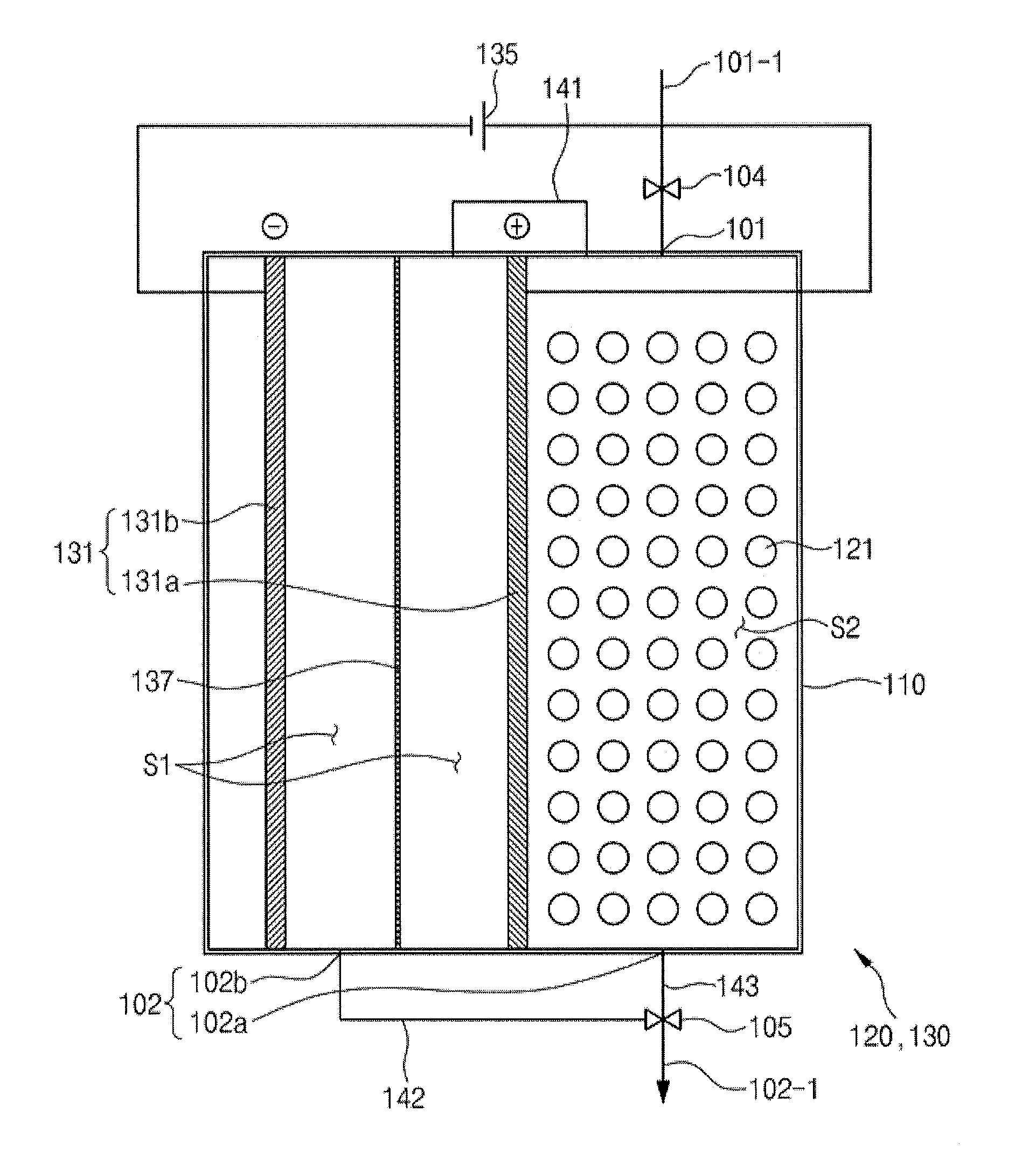
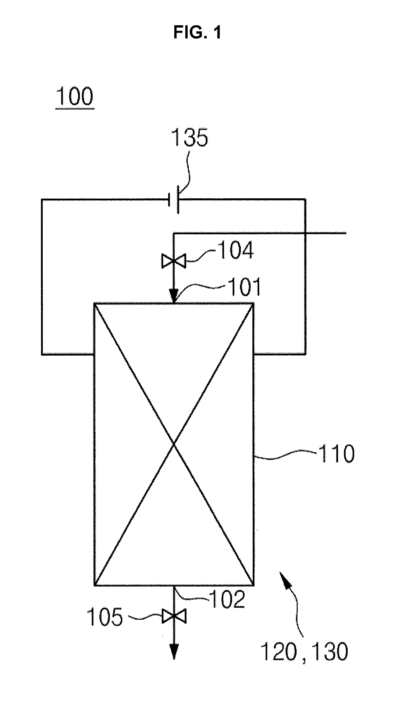
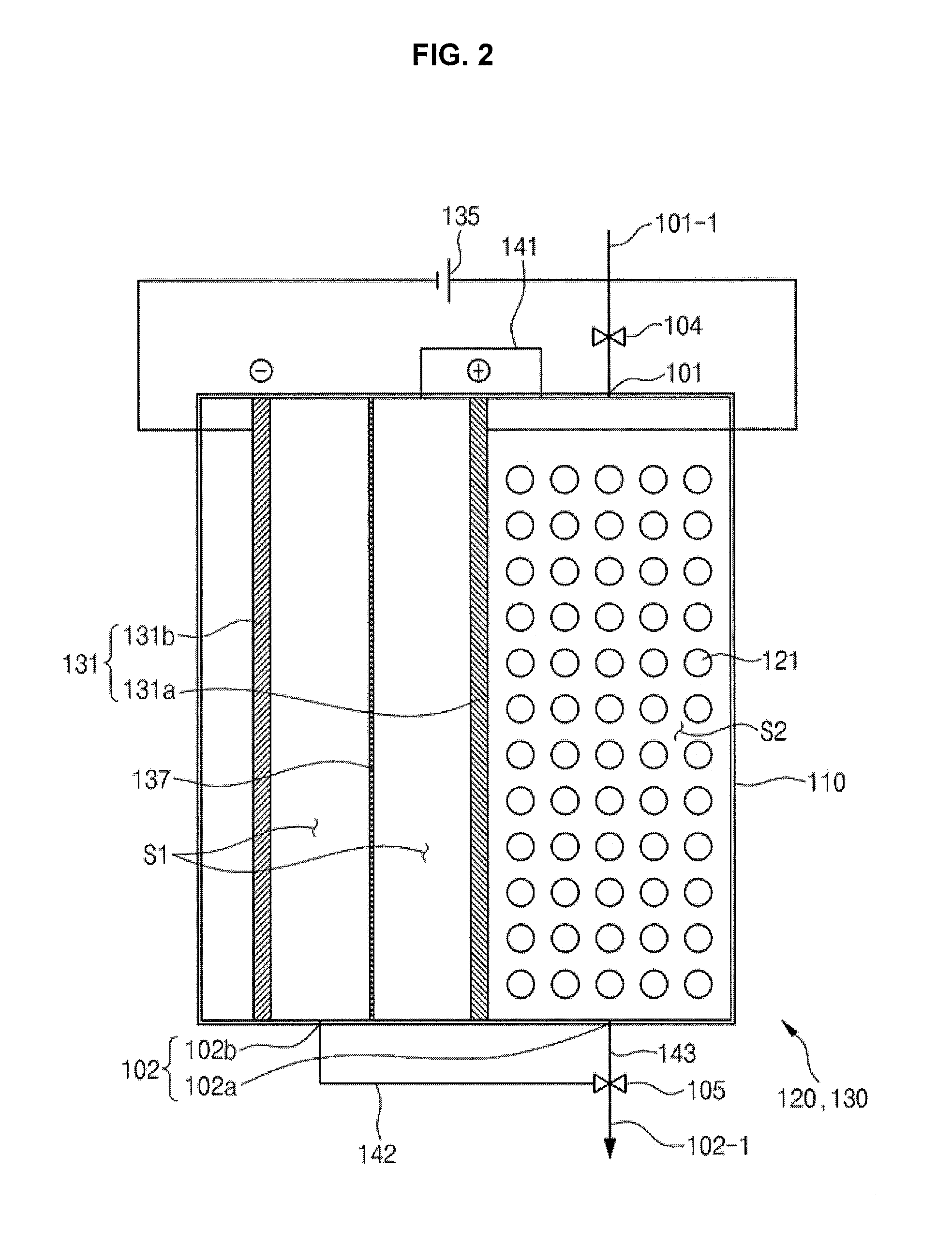
[0040]Embodiments of the present disclosure relate to a softening apparatus that softens raw water containing a hardness component. For convenience of description, the present disclosure describes different forms of water as follows: water containing a hardness component introduced into the softening apparatus is referred to as raw water; raw water, from which the hardness component has been removed, discharged from a softening unit is referred to as soft water; water having a high concentration of hydrogen ions (H+), generated by an anode during electrolysis, and supplied to an ion exchange body is referred to as regeneration water; water having a high concentration of hydroxyl ions (OH−), generated by a cathode during electrolysis, and discharged from the softening ...


PUM

PropertyMeasurementUnit
shapeaaaaaaaaaa
structureaaaaaaaaaa
hardnessaaaaaaaaaa

Abstract

A softening apparatus in which resistance applied between electrodes is decreased to reduce power consumption. The softening apparatus includes a regeneration unit and a softening unit. The regeneration unit includes at least one anode and cathode in a first space which generate regeneration water containing hydrogen ions (H+). The softening unit is disposed in a second space partitioned from the first space and includes an ion exchange body regenerated by the regeneration water.

Description

CROSS-REFERENCE TO RELATED APPLICATIONS[0001]This application claims the benefit of Korean Patent Application No. 10-2014-0015313, filed on Feb. 11, 2014 in the Korean Intellectual Property Office, the disclosure of which is incorporated herein by reference.BACKGROUND[0002]1. Field[0003]Embodiments of the present disclosure relate to a softening apparatus that is regenerated using an electrochemical method.[0004]2. Description of the Related Art[0005]When detergent is used to remove non-polar contaminants from electric home appliances (a washer, a dishwasher, etc.) using water, cleaning performance may be deteriorated due to hardness of the water and the electric home appliances may be contaminated due to microorganisms propagating in the water and a scale component.[0006]In order to prevent cleaning performance from being deteriorated due to hardness of the water, a heater may be used to increase solubility of the detergent, a hardness component may be removed using an ion exchange...

Claims


Application Information

Patent Timeline
13 Aug 2015
Publication
US20150225260A1
IPC
C02F1/42
CPC
C02F1/42; C02F2303/16; C02F2001/425; C02F2103/002; C02F2201/46115; B01J49/30; B01J49/75; C02F1/4618
Inventors
JUNG, MOON IL; PARK, HEE-JIN