Supercharge Your Innovation With Domain-Expert AI Agents!

Electrodeionization module and apparatus

a technology of electrodeionization module and electrodeionization process, which is applied in the direction of liquid/fluent solid measurement, fluid pressure measurement, peptide, etc., can solve the problems of low energy efficiency of the deionization process, high material cost, and available for exchange, and achieve the effect of reducing current efficiency

Active Publication Date: 2015-08-13
MERCK PATENT GMBH
View PDF1 Cites 1 Cited by
  • Summary
  • Abstract
  • Description
  • Claims
  • Application Information

AI Technical Summary

Benefits of technology

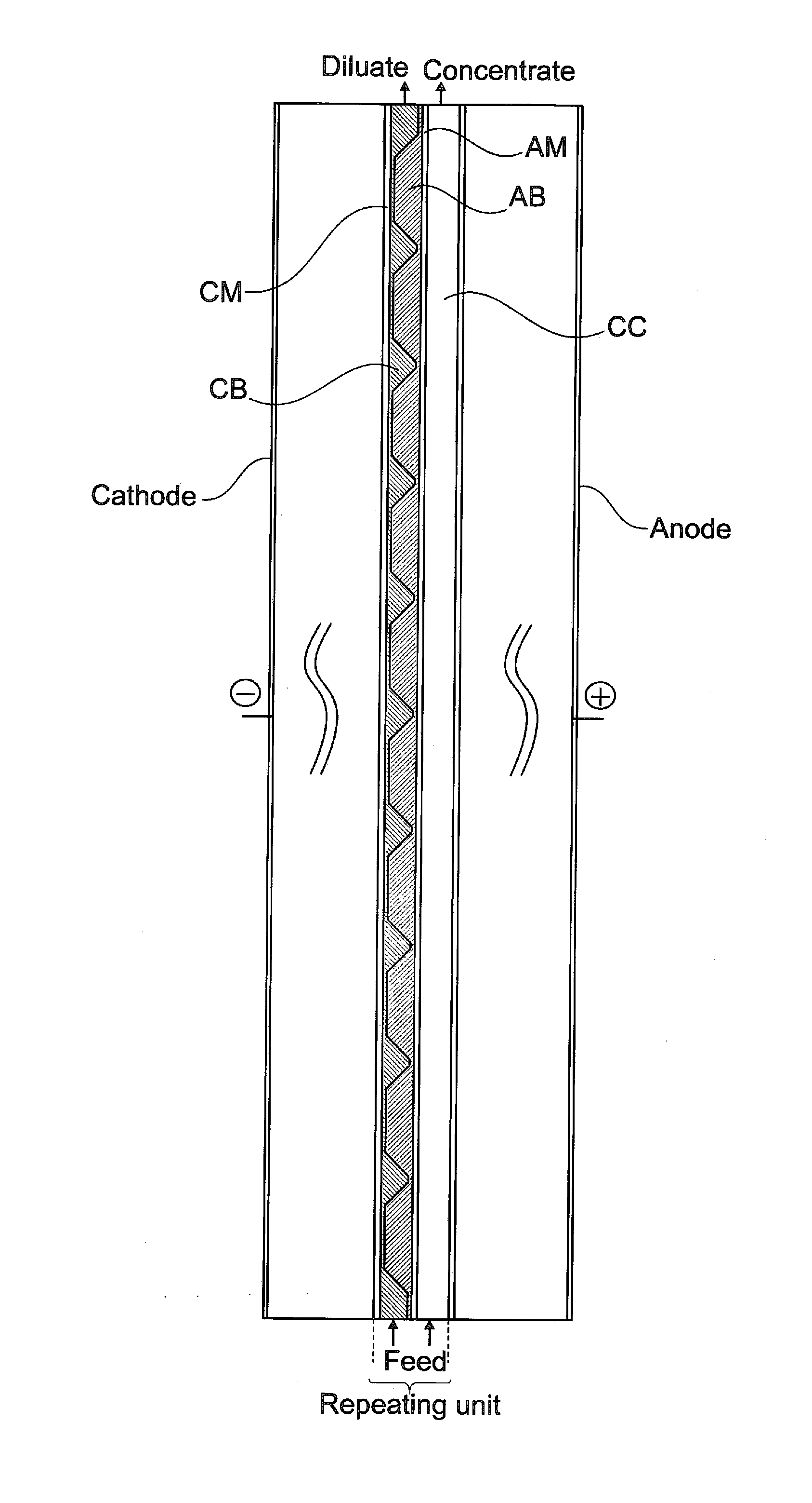
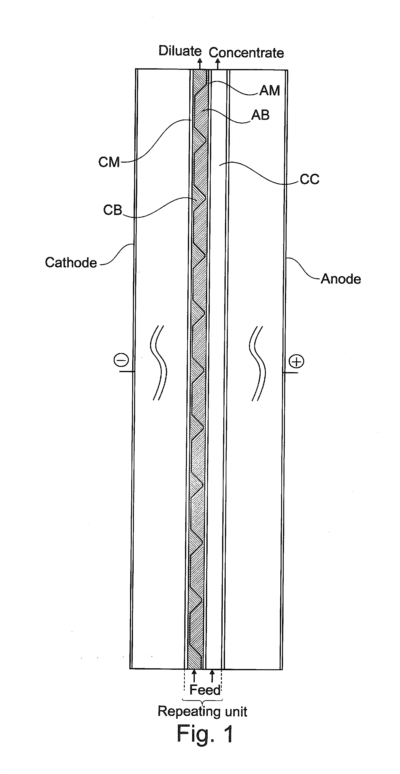
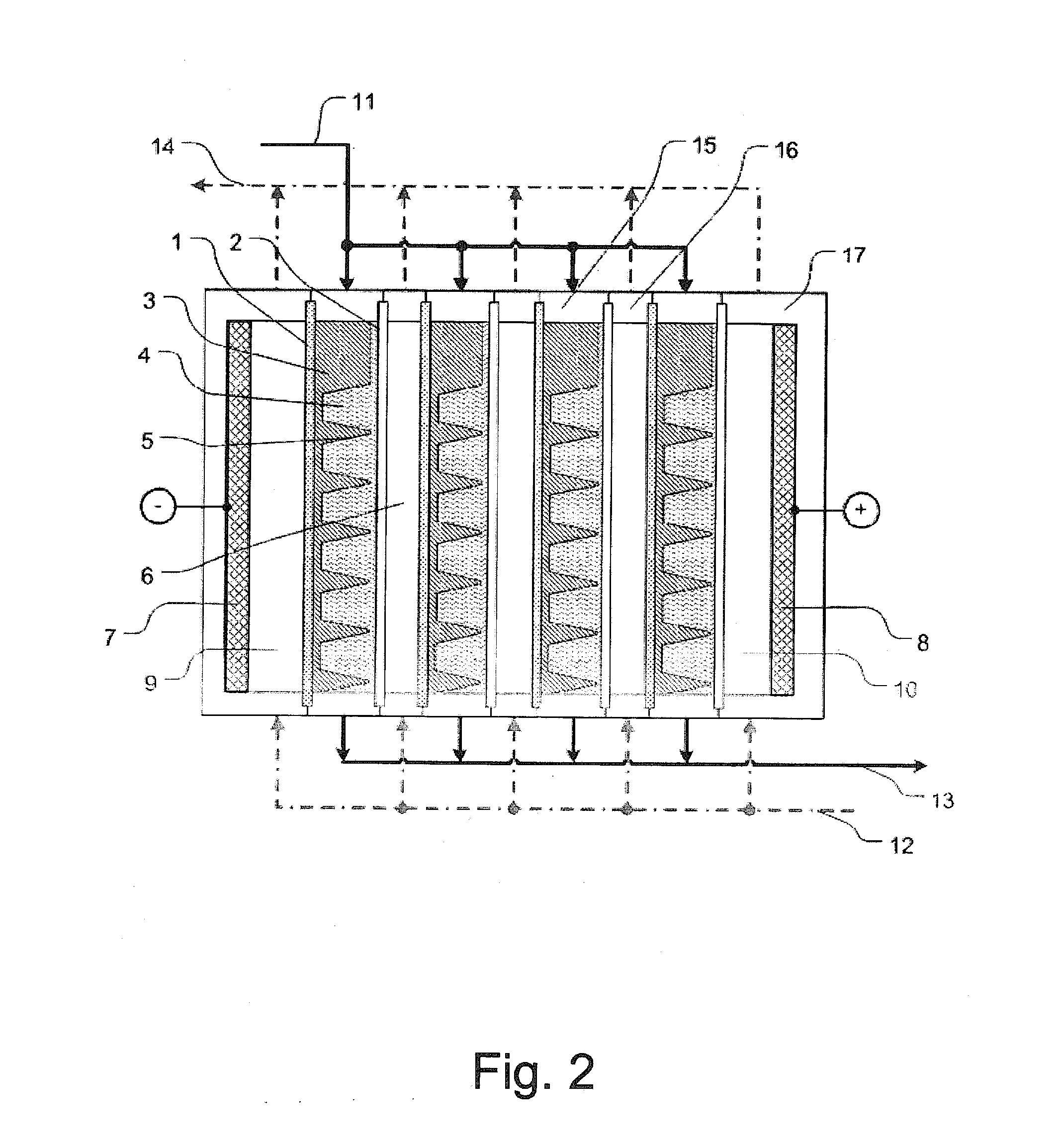
The present invention provides an EDI module and apparatus that benefits from the use of flow-through ion-exchange materials, which offer an intensified purification process and special arrangements of ion-exchange materials that overcome the drawbacks of known modules. The module design allows for a decreased complexity of manufacturing and assembly, efficient purification, increased current efficiency, and improved performance and ease of assembly compared to layered grafted materials. Overall, the invention offers a laboratory water purification system that can provide ultra-pure water on demand at low costs of both manufacture and operation and with unprecedented efficiency.

Problems solved by technology

Together with the fact that compartments with layers parallel to membranes are relatively thin, e.g. 3 mm-5 mm, the assembly will require a relatively high membrane area per volume of water produced and result in relatively high material cost.
It is considered that the regeneration of materials with such orientation in the electric field may require a relatively high potential drop to be applied and may result in a relatively low energy efficiency for the deionization process.
As a further disadvantage of the technique described in US 2006 / 0091013, due to the orientation in a plurality of thin layers where H+ and OH− ions are migrating in opposite directions, some of them can be driven by concentration difference to the interface between the counterpolar layers where they will recombine to water and thus will not be available for exchange with ionic and ionizable contaminants from water.
In a similar way the salt ions, which are already removed from water and migrate inside corresponding ion-exchange material can recombine on the interface between counterpolar grafted materials and thus be rejected back into water, thereby decreasing the current efficiency of the purification process.
This further decreases the current efficiency and provokes strong local pH variations on the surface of the corresponding membrane in the concentrate compartment, which might be unwished due to the risk of scaling formation or materials degradation.

Method used


Image

  • Electrodeionization module and apparatus
  • Electrodeionization module and apparatus
  • Electrodeionization module and apparatus

Examples


first embodiment

[0115]In the laboratory water purification system according to the present invention, water after pretreatment and reverse osmosis (RO) purification is collected in a tank.

[0116]The EDI module or the EDI apparatus according to the present invention (in the following also simply called EDI module) is located downstream the tank and can be operated in two modes:

[0117]1) regeneration—recirculation of water between the tank and the EDI module while water in the tank is purified to a set level and the ion-exchange materials of the module are transformed in substantially regenerated form;

[0118]2) dispensing—water from the tank is pumped through the EDI module and produced pure or ultrapure water is used at flow rate of dispensing.

[0119]Preferably, the RO-permeate enters the tank from the top, while an increase of interface water / air, e.g. using spray ball or aerator, will intensify the release of CO2 from water oversaturated with CO2. Such partial degassing would facilitate the work of th...

second embodiment

[0124]In the laboratory water purification system according to the present invention, the water purification system comprises mainly pretreatment, RO or NF (nanofiltration) and the EDI modules according to the present invention without any intermediate water storage tank for the EDI diluate.

[0125]The water produced by this system can be directly supplied to the point of use with only an optional purifier downstream the EDI module. This laboratory water purification system is advantageous to currently known systems, since it requires less components.

[0126]An example of this embodiment is schematically illustrated in FIG. 9. Here a part of the laboratory water purification system utilizing an EDI module according to the present invention is shown where the RO and EDI purification steps are designed to deliver water to the point of use with sufficient flow rate without an intermediate storage reservoir.

third embodiment

[0127]In the laboratory water purification system according to the present invention, the laboratory water purification system contains an EDI module according to the present invention and comprises an RO-step upstream the EDI module, wherein by switching from a production to a stand-by mode a part of the water produced by EDI or by RO is diverted to the inlet of the RO to perform an RO-flush.

[0128]During a stand-by period, an exchange of ions between the permeate and the reject side of an RO-membrane occurs, which leads to a contamination of the permeate side when tap water or water with a high ionic load is used as feed. Conventionally, a certain rinsing time (typically from some seconds to few minutes) is required to rinse out the thus contaminated water from the permeate side and then divert the permeate of a sufficient low conductivity for downstream EDI-purification. In order to avoid this rinsing and to start the production once required the laboratory water purification syst...


PUM

PropertyMeasurementUnit
lengthaaaaaaaaaa
angleaaaaaaaaaa
angleaaaaaaaaaa

Abstract

The present invention relates to an improved electrodeionization (EDI) module and apparatus adapted to transfer ions present in a liquid under the influence of an electric field.

Description

FIELD OF THE INVENTION[0001]The present invention relates to an improved electrodeionization (EDI) module and apparatus adapted to transfer ions present in a liquid under the influence of an electric field. Specifically, the invention relates to an EDI apparatus adapted to purify aqueous liquids for the production of water of high purity or ultra-pure water and a method for purifying a liquid. The present invention further relates to a laboratory water purification system utilizing the EDI module or apparatus.BACKGROUND OF THE INVENTION[0002]Electrodeionization (EDI) is a process for removing ions from liquids, such as water, by sorption of these ions to a material capable of exchanging these ions either for hydrogen ions (for cations) or hydroxide ions (for anions) and removal of the sorbed ions by the application of an electric field between an anode and a cathode.[0003]A typical EDI module has at least one diluate compartment through which the liquid to be processed is passed and...

Claims


Application Information

Patent Timeline
Patent Type & Authority Applications(United States)
IPC IPC(8): C02F1/469B01D61/48
CPCC02F1/4695B01D61/48B01D2325/42C02F2201/46C02F2103/04B01D61/485C02F1/32C02F1/441C02F1/442C02F2303/16
Inventor GRABOWSKI, ANDREJGROSS, JULIEN
Owner MERCK PATENT GMBH
Features
  • R&D
  • Intellectual Property
  • Life Sciences
  • Materials
  • Tech Scout
  • Unparalleled Data Quality
  • Higher Quality Content
  • 60% Fewer Hallucinations
Learn More