Apparatus and system for converting wave energy based on oscillating water column type

a technology of oscillating water column and apparatus, which is applied in the direction of mechanical equipment, machines/engines, electric generator control, etc., can solve the problems of conventional energy converting apparatus, easy damage or swept away, complicated structure, etc., and achieve fast movement performance, high energy conversion efficiency, and maximum amplitude

Inactive Publication Date: 2015-08-13
SEUNG KWAN SONG
View PDF2 Cites 5 Cited by
  • Summary
  • Abstract
  • Description
  • Claims
  • Application Information

AI Technical Summary

Benefits of technology

[0016]Furthermore, since flow of fluid is concentrated on one place due to the kinematic design, it is possible to maximize the amplitude, thereby guaranteeing a fast movement performance. Accordingly, it is possible to achieve a high energy conversion efficiency even when using a small generator.
[0017]In addition, since there is no need to secure additional space for a chamber for resonance conditions, it is possible to reduce the volume, obtain a high volumetric efficiency, and further, it is possible to reduce the risk of damage and loss caused by limitation factors such as waves.
[0018]Furthermore, since the direction of water pressure acting on the main body is vertically upwards, the main body may be suspended underwater, thereby saving installation costs.
[0019]In addition, it is possible to realize a low dry weight, simple structure, and high volumetric efficiency, thereby reducing the manufacturing costs, and since the dry weight is low, it becomes easy to transfer the apparatus, and since the components are made of pipes, repair and maintenance is also easy.

Problems solved by technology

However, conventional oscillating water column type energy converting apparatuses are installed on the surface of water, and may thus be easily damaged or swept away in cases of by marine disasters such as storms and tidal waves etc.
Herein, since additional mechanical components such as a bushing and an LM (Linear Motion) for restricting the movement of the apparatus are needed, the structure becomes complicated.
Furthermore, conventional energy converting apparatuses such as those disclosed in International Patent Publication in WO 2008 / 149084 (published on Dec. 11, 2008) cannot be suspended in water because the direction of water pressure acting on the main body is vertically downwards.

Method used


Image

  • Apparatus and system for converting wave energy based on oscillating water column type
  • Apparatus and system for converting wave energy based on oscillating water column type
  • Apparatus and system for converting wave energy based on oscillating water column type

Examples


Embodiment Construction

[0036]Certain exemplary embodiments are described in higher detail below with reference to the accompanying drawings.

[0037]In the following description, like drawing reference numerals are used for the like elements, even in different drawings. The matters defined in the description, such as detailed construction and elements, are provided to assist in a comprehensive understanding of exemplary embodiments. However, exemplary embodiments can be practiced without those specifically defined matters. Also, well-known functions or constructions are not described in detail since they would obscure the application with unnecessary detail.

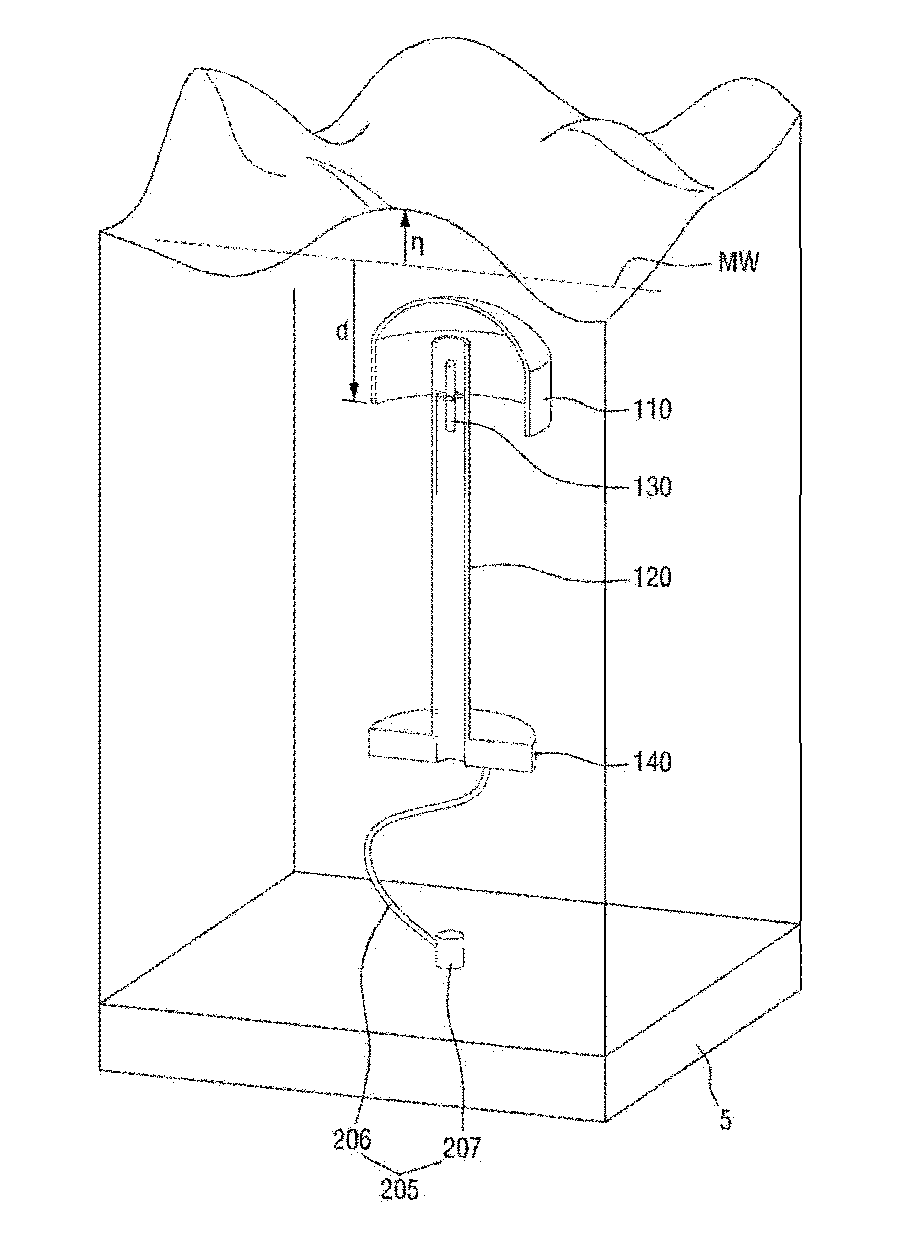
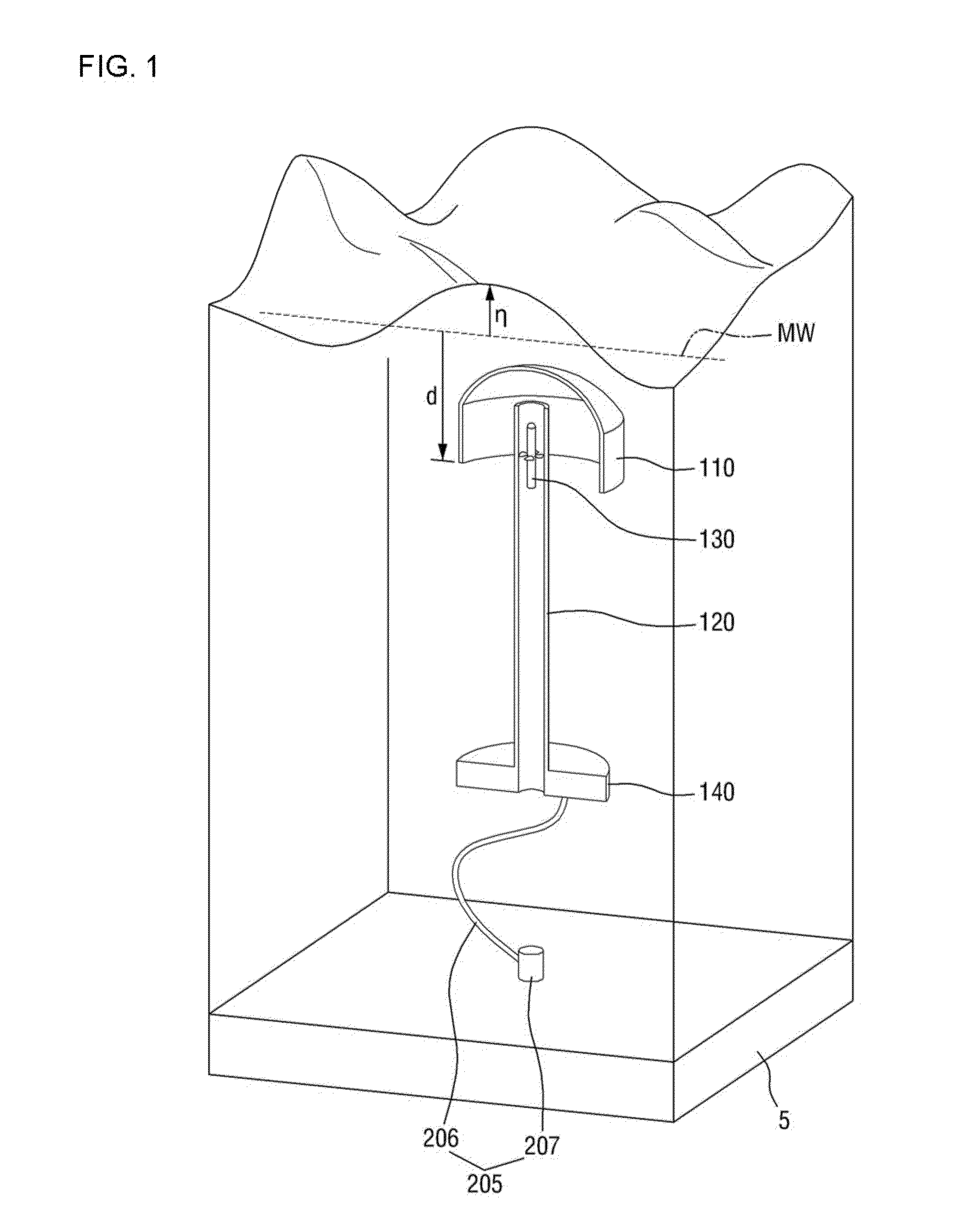
[0038]FIG. 1 is a cut skewed view of an oscillating water column type wave energy converting apparatus according to an exemplary embodiment of the present disclosure.

[0039]Referring to FIG. 1, an oscillating water column type energy converting apparatus 100 according to an exemplary embodiment of the present disclosure is disposed underwater by a mooring ...


PUM


Abstract

Provided herein is an oscillating water column type wave energy converting apparatus that is suspended underwater by a mooring device and system thereof, the apparatus and system comprising an damping plate connected to the mooring device; a post with a hollow of which both ends are open, the post extending vertically upwards from the mooring device; a turbine disposed inside the hollow of the post; and a housing of which its lower end is open and which is disposed at an upper portion of the post, wherein the turbine is rotated by air that flows according to changes in water level inside the hollow of the post.

Description

BACKGROUND OF THE INVENTION[0001]1. Field of the Invention[0002]Methods and apparatuses consistent with the exemplary embodiments relate to an apparatus and system for converting wave energy based on oscillating water column type, and more particularly to an oscillating water column type apparatus for converting wave energy that may be installed in a simple structure under water by satisfying resonance conditions depending on only a hydraulic spring constant and added mass by movement of water, and a system thereof.[0003]2. Description of the Prior Art[0004]Of ocean energies, wave energy refers to the oscillating energy of seawater caused by wind. Waves refer to the reciprocating movement of seawater moving up and down or left and right, which are different from tidal currents. Wave power generation refers to getting electric energy from wave energy, and is currently in the spotlight as a future environmentally friendly energy source. More specifically, periodical up and down moveme...

Claims


Application Information

Patent Timeline
Patent Type & Authority Applications(United States)
IPC IPC(8): F03B13/14F03B13/24F01D15/10
CPCF03B13/142F03B13/24F01D15/10Y02E10/30
Inventor SONG, SEUNG KWAN
Owner SEUNG KWAN SONG
Why Eureka
Try Eureka