Bellows type mechanical seal

Inactive Publication Date: 2015-08-13
EAGLE INDS
View PDF8 Cites 5 Cited by
  • Summary
  • Abstract
  • Description
  • Claims
  • Application Information

AI Technical Summary

Benefits of technology

The present invention provides a bellows type mechanical seal that improves the corrosion resistance of a bellows assembly by integrating a retainer, bellows and collar. The use of an anti-corrosion coating film, such as chromium nitride, ensures excellent corrosion resistance. The retainer is made of a material with a coefficient of thermal expansion close to that of the seal ring, reducing stress change and improving sealing efficiency. If the seal ring is separated from the retainer, sliding torque between the seal ring and mating ring is minimized, resulting in a stable sealing performance even during minimal vibration.

Problems solved by technology

For the purpose of preventing corrosion, anti-corrosion plating should be done on the surface of the retainer and the welded portion thereof, but when the retainer is welded to the bellows after being plated, there is a fear that the plating of the welded portion may peel off, or defective plated portions such as blow holes, cavities, etc., may occur, thus resulting in that the welded portion may be corroded.
On the other hand, in cases where plating is carried out on the retainer and the welded portion after welding, the bellows, if plated, will change its property, so it is necessary to mask the bellows, but masking work is troublesome, and masking may be insufficient so that the bellows will also be plated, or the welded portion is not plated, as a result of which any sufficient anti-corrosion effect may not be obtained.
Therefore, under highly corrosive environments, 42% Ni—Fe will not be able to be used as a retainer material, and hence, materials to be used are limited.

Method used


Image

  • Bellows type mechanical seal
  • Bellows type mechanical seal
  • Bellows type mechanical seal

Examples


first embodiment

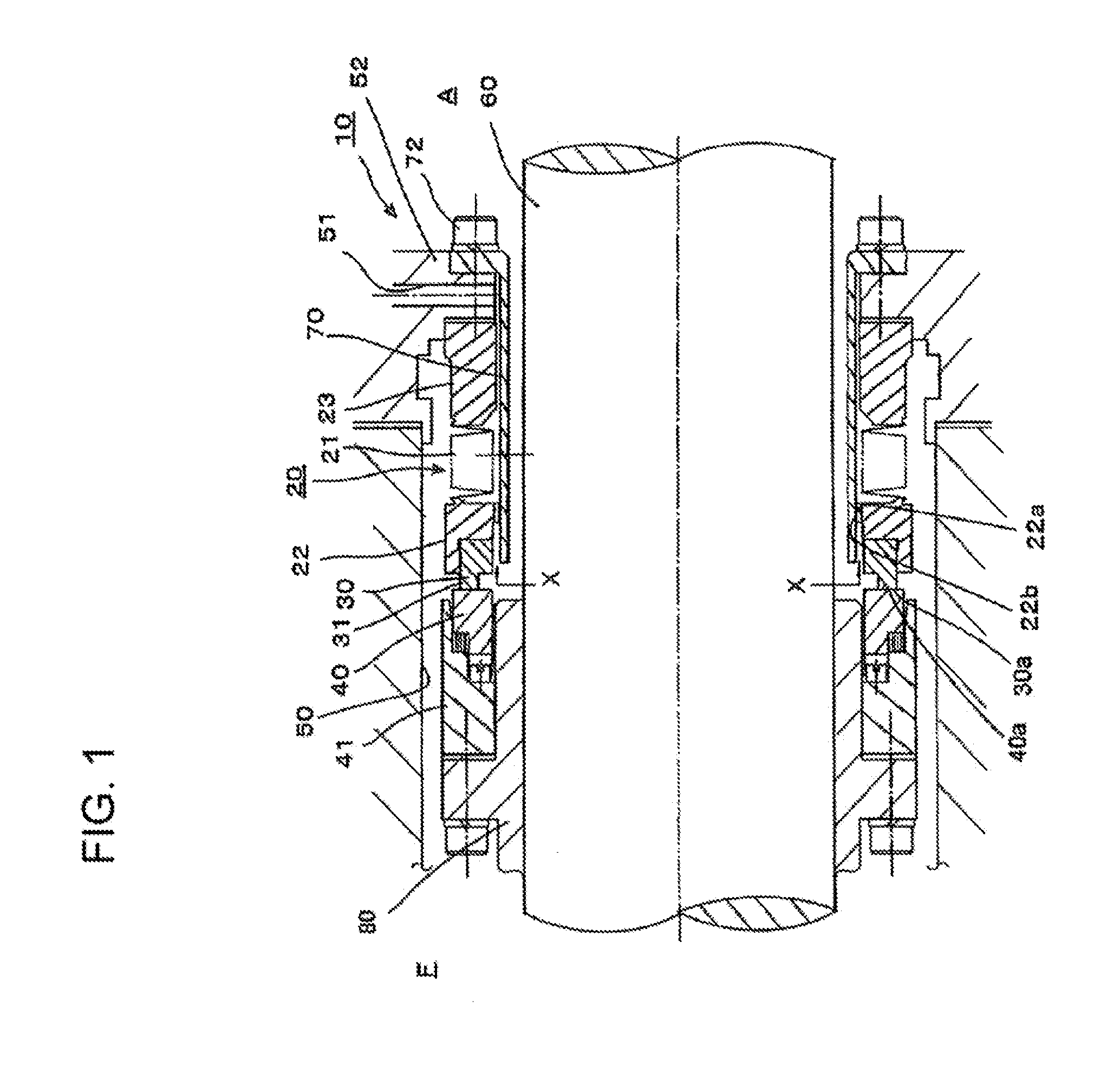
[0030]FIG. 1 shows a bellows type mechanical seal related to a first embodiment of the present invention, wherein 10 denotes the whole of the bellows type mechanical seal.

[0031]That is, this bellows type mechanical seal 10 serves to provide a sealing between a rotating shaft 60 and a housing 50, and is provided with a seal ring 30 and a mating ring 40 which is arranged in opposition to the seal ring 30 so as to be in sliding contact therewith. In this embodiment, the bellows type mechanical seal 10 is a stationary type mechanical seal, the construction of which is such that the seal ring 30 is supported by the housing 50 through a seal cover 52, and the mating ring 40 is supported on the rotating shaft 60 so as to rotate together with the rotating shaft 60. In addition, a fixed sleeve 80 is fitted and fixed to the rotating shaft 60, and a retainer 41 holding the mating ring 40 is fixedly secured to this fixed sleeve 80. In this figure (FIG. 1), assuming that the outside of the seal ...

second embodiment

[0052]Next, a second embodiment of the present invention will be described.

[0053]FIG. 3 shows a bellows type mechanical seal related to the second embodiment of the present invention. In the following explanation, only different features will be described, and the same symbols will be given to the same components as those of the first embodiment, and the explanation thereof will be omitted.

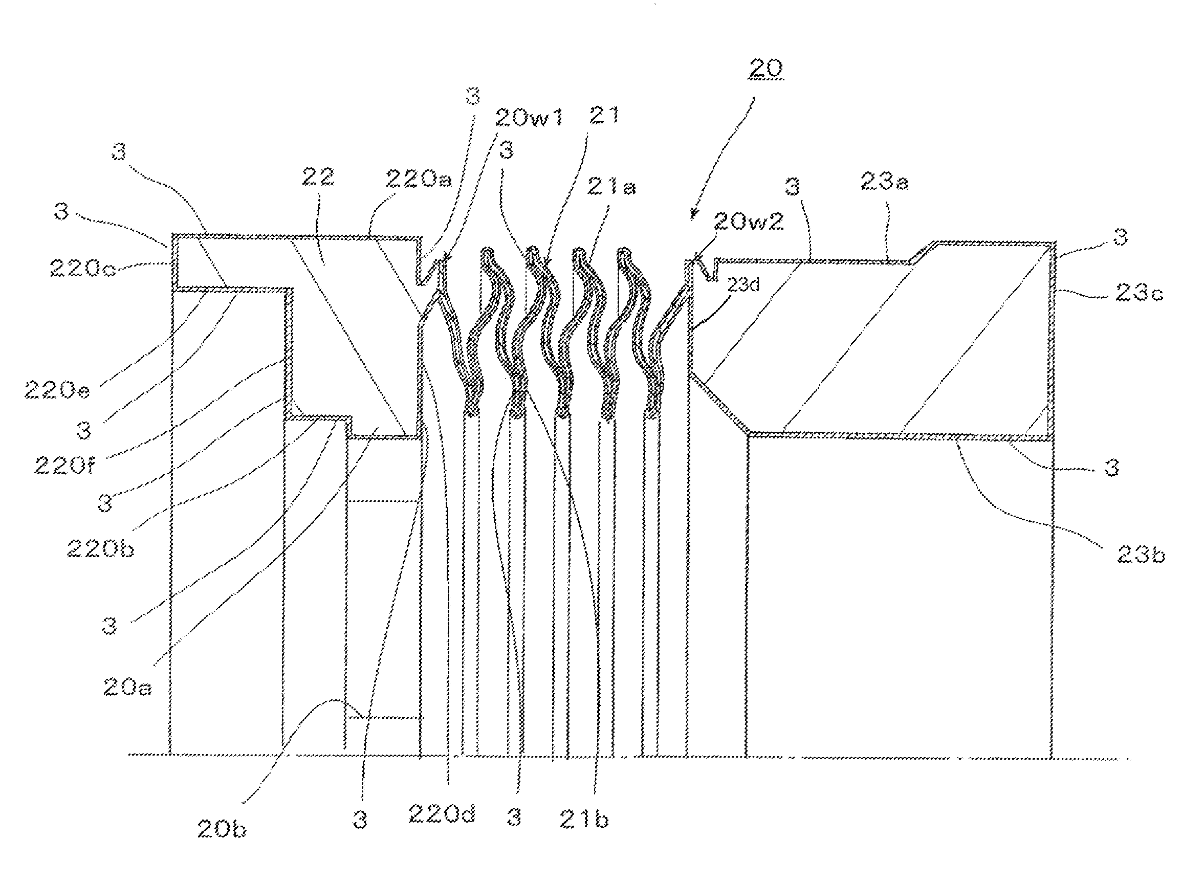
[0054]In this second embodiment, it is not a construction in which the seal ring 30 is fitted to the retainer 22, but a coupling structure in which the seal ring 30 is separated from the retainer 22, and a retainer-side end face of the seal ring 30 and a seal ring-side end face of the retainer 22 are in close contact with each other in a manner to be mutually freely slidable relative to each other in a circumferential direction. Hereinafter, this coupling structure is called a lap joint part 90.

[0055]That is, an annular nose 32 is formed to protrude on the retainer-side end face of the seal ring 3...


PUM


Abstract

A bellows type mechanical seal including a sealing ring and a mating ring, wherein either one of the sealing ring or the mating ring is retained in a housing and the other one is mounted on a shaft and wherein the sealing ring is supported by a bellows and the bellows has a retainer welded thereto on one of the sides for retaining the sealing ring and a collar welded on the other side to form a bellows assembly, is characterized in that the entire surface of the bellows assembly is covered by an erosion-resistant film formed by the physical vapor deposition, such as ion-plating.

Description

CROSS REFERENCE TO RELATED APPLICATION[0001]This application is a continuation-in-part of U.S. application Ser. No. 13 / 258,827, filed Sep. 22, 2011, which was the national stage of International Application No. PCT / JP2010 / 054106, filed Mar. 11, 2010, the entireties of which are incorporated herein by reference.FIELD OF THE INVENTION[0002]The present invention relates to a mechanical seal which can be widely applied to a variety of kinds of fields including oil refining, petrochemistry, steel making chemistry, chemicals, food, and general industrial machinery, and in particular, relates to a bellows type mechanical seal using a bellows as a secondary seal.BACKGROUND OF THE INVENTION[0003]Such a kind of conventional bellows type mechanical seal, when taking an example of a stationary form, is provided with a seal ring which is held by a bellows, and a mating ring which is arranged in opposition to the seal ring in a manner as to slidably contact therewith, wherein it is constructed su...

Claims


Application Information

Patent Timeline
IPC IPC(8): F16J15/36F16J15/34
CPCF16J15/3496F16J15/363F16J15/348F16J15/36F16J15/34
Inventor TAKAHASHI, HIDEKAZU
Owner EAGLE INDS
Why Eureka
Try Eureka