Waveguide tube slot antenna and wireless device provided therewith

a wireless device and waveguide tube technology, applied in the direction of linear waveguide fed arrays, instruments, using reradiation, etc., can solve the problem of liable change in the sensing capability (solving power) of laser radars, and achieve the effect of low cost, high degree of freedom in design, and high performan

Active Publication Date: 2015-08-13
NTN CORP
View PDF3 Cites 23 Cited by
  • Summary
  • Abstract
  • Description
  • Claims
  • Application Information

AI Technical Summary

Benefits of technology

[0029]As described above, according to the first aspect of this application, the waveguide tube slot antenna that is high in performance and high in degree of freedom in design (degree of freedom in changing the antenna performance) can be subjected to mass production at low cost.
[0030]Further, according to the second aspect of this application, the waveguide tube slot antenna with the increased antenna performance can be provided at low cost.

Problems solved by technology

However, a sensing capability (resolving power) of the laser radar is liable to change due to external factors such as dirt on a vehicle and weather conditions.

Method used


Image

  • Waveguide tube slot antenna and wireless device provided therewith
  • Waveguide tube slot antenna and wireless device provided therewith
  • Waveguide tube slot antenna and wireless device provided therewith

Examples


first embodiment

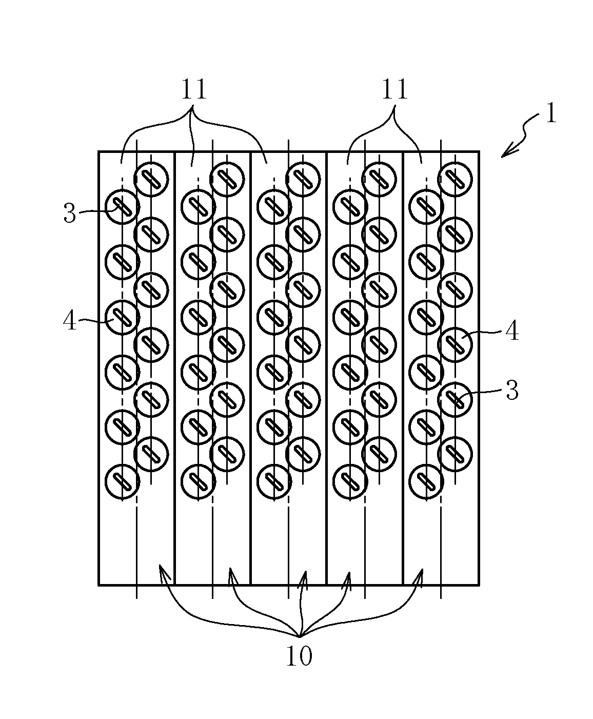
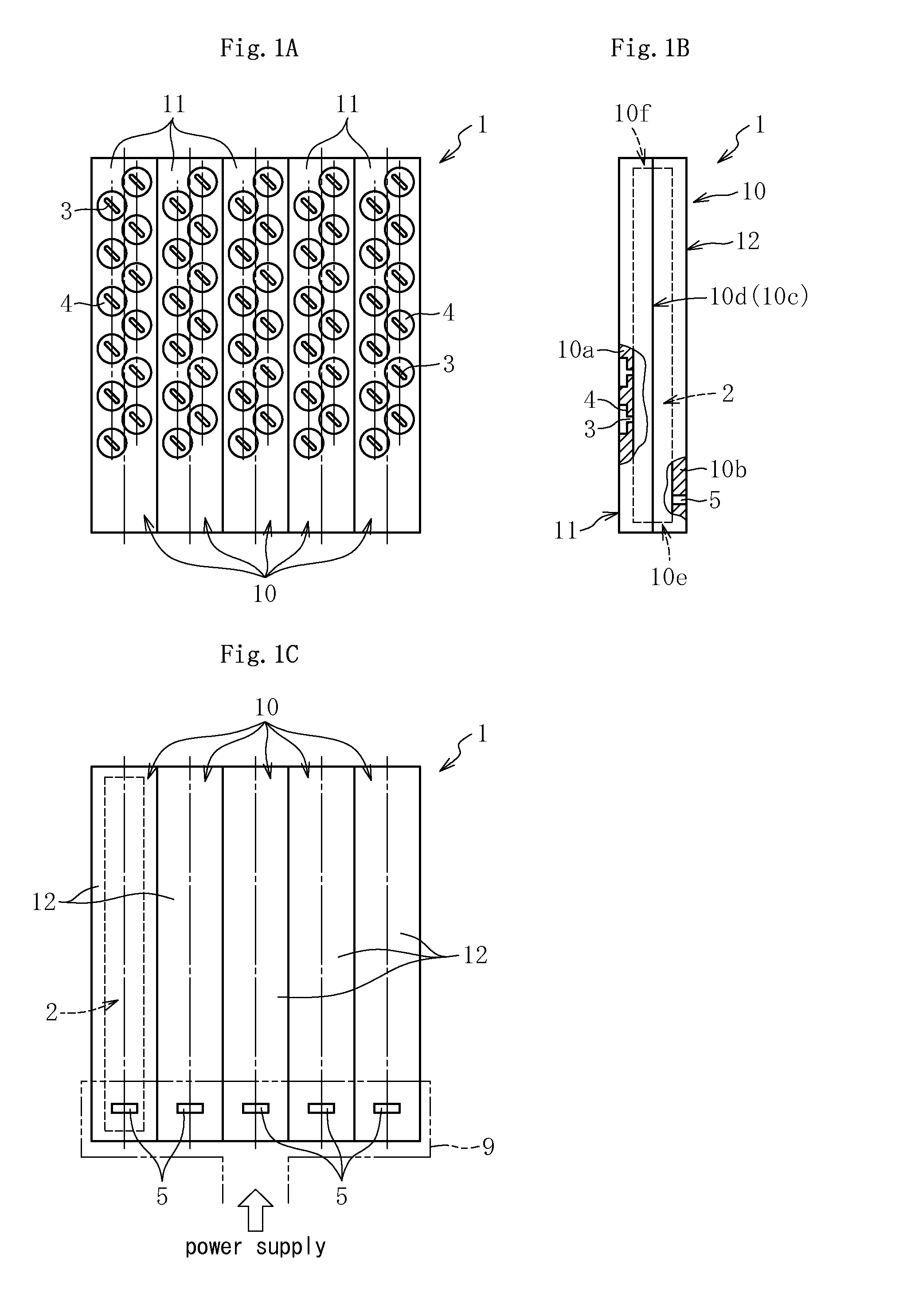
[0056]FIG. 1A to FIG. 1C illustrate a plan view, a side view, and a back view of a waveguide tube slot antenna 1 according to the first aspect, respectively. The waveguide tube slot antenna 1 illustrated in FIG. 1A to FIG. 1C constructs, for example, an antenna part of a radar system (on-vehicle radar system) mounted to an automobile for the purpose of safe driving support or the like, and is formed by connecting a plurality of (five in the example of FIG. 1A to FIG. 1C) waveguide tubes 10 in parallel with each other. Each waveguide tube 10 comprises one waveguide 2 through which a radio wave flows in an inside thereof as illustrated in FIG. 1B or the like. Accordingly, the waveguide tube slot antenna 1 comprises five waveguides 2 arranged in parallel with each other. Note that, of the five waveguide tubes 10, for example, the waveguide tube 10 located in a central part can function as an antenna for transmission, and the two waveguide tubes 10 arranged on both sides in a width dire...

second embodiment

[0103]FIG. 11A to FIG. 11D illustrate the waveguide tube slot antenna 31 according to the second aspect. In the waveguide tube slot antenna 31 according to this embodiment, as illustrated in FIG. 11A, two radiating slot rows each obtained by arranging the plurality of radiating slots 33 along the tube axis direction at predetermined intervals are provided in the width direction of the waveguide tube 40, and at the same time, the radiating slot 33 forming one of the radiating slot rows and the radiating slot 33 forming the other radiating slot row are located in mutually different positions in the tube axis direction. To briefly describe, in the waveguide tube slot antenna 31 according to this embodiment, the plurality of radiating slots 33 (and recess parts 34) are arranged in a staggered shape.

[0104]As illustrated in FIG. 11B, the waveguide tube 40 that forms the waveguide tube slot antenna 31 according to this embodiment is a rectangular waveguide tube comprising the pair of narro...

third embodiment

[0107]FIG. 12 is a transverse sectional view of the waveguide tube slot antenna 31 according to the second aspect, and is a modification example of the embodiment illustrated in FIG. 11. The waveguide tube slot antenna 31 according to this embodiment is different from the waveguide tube slot antenna 31 according to the embodiment illustrated in FIG. 11 mainly in that the branching wall 40g is also comprising the coupling part C formed by fitting (press-fitting) the projection part 46 into the depression part 45.


PUM


Abstract

Provided is a waveguide tube slot antenna (1) including: a plurality of waveguides (2) arranged in parallel with each other; a plurality of radiating slots (3) formed along each of the plurality of waveguides (2); and a plurality of waveguide tubes (10) connected in parallel with each other, in which the plurality of waveguide tubes (10) each include a first waveguide tube forming member (11) and a second waveguide tube forming member (12) each having a transverse section having a shape with an end, the first waveguide tube forming member and the second waveguide tube forming member being configured to define one of the plurality of waveguides (2) by being connected to each other.

Description

TECHNICAL FIELD[0001]The present invention relates to a waveguide tube slot antenna and a wireless device provided therewith.BACKGROUND ART[0002]In recent years, a radar device (radar system) serving as a kind of wireless device is sometimes mounted to an automobile for the purpose of safe driving support or the like (for example, collision prevention). As an on-vehicle radar device of this kind, there is a device that uses a laser radar as a sensor or a device that uses a millimeter wave radar as a sensor. However, a sensing capability (resolving power) of the laser radar is liable to change due to external factors such as dirt on a vehicle and weather conditions. Therefore, in recent times, there has been more often employed a millimeter wave radar whose resolving power is hard to change due to the external factors and which can stably exhibit a desired resolving power at all times. Note that, the millimeter wave represents an electromagnetic wave having a wavelength of from 1 to ...

Claims


Application Information

Patent Timeline
Patent Type & Authority Applications(United States)
IPC IPC(8): H01Q13/18G01S13/931
CPCH01Q13/18G01S7/03G01S13/886G01S13/931H01Q21/005H01Q1/3233H01Q13/22H01Q21/0043H01Q21/0087H01Q13/10H01Q13/20H01Q21/06H01Q21/061
Inventor SONOZAKI, TOMOKAZUNODA, HIROYUKIMORI, NATSUHIKO
Owner NTN CORP
Why Eureka
Try Eureka