
Method of Manufacturing a Test Socket Body of an Impedance-Matched Test Socket

a technology of impedance-matched test sockets and test socket bodies, which is applied in the field of manufacturing of the test socket body of an impedance-matched test socket, can solve the problems of fhst testing being difficult, the working frequency of ic devices creating a challenge, and the traditional test sockets made of insulative materials such as plastics and ceramics, and cannot prevent contactor crosstalk

Inactive Publication Date: 2015-08-20
WOODEN TIM +1
View PDF3 Cites 15 Cited by
  • Summary
  • Abstract
  • Description
  • Claims
  • Application Information

AI Technical Summary

Benefits of technology

The invention is a method that simplifies the manufacturing process of a probe holder by using standard parts and simultaneous multiposition treatment. The method involves inserting pogo pins of different types into a probe holder and other parts, and securing them in place to create a complete test socket body. The technical effects of this method include reducing manufacturing steps and accelerating production.

Problems solved by technology

The increased working frequency of IC devices creates a challenge to FHST testing because traditional test sockets made out of insulative material, such as plastics and ceramics, do not perform well.
FHST test sockets made of insulative materials with high or low dielectric permittivity cannot prevent contactor crosstalk because the wavelength becomes comparable to the length of the contactors whereby the contactors behave as antennas and propagate radio frequency.
However, manufacturing of testers of the aforementioned type is rather complicated since the manufacturing process involves high precision operations and the use of expensive equipment of high accuracy.
The manufacturing and assembling of such a test socket is expensive and complicated since the process involves manufacturing of a plurality of small different parts which have to inserted one by one into the respective holes of the upper housing.
This structure does not provide complete screening of the pogo pins and there cannot completely prevent cross talking.

Method used


Image

  • Method of Manufacturing a Test Socket Body of an Impedance-Matched Test Socket
  • Method of Manufacturing a Test Socket Body of an Impedance-Matched Test Socket
  • Method of Manufacturing a Test Socket Body of an Impedance-Matched Test Socket

Examples


Embodiment Construction

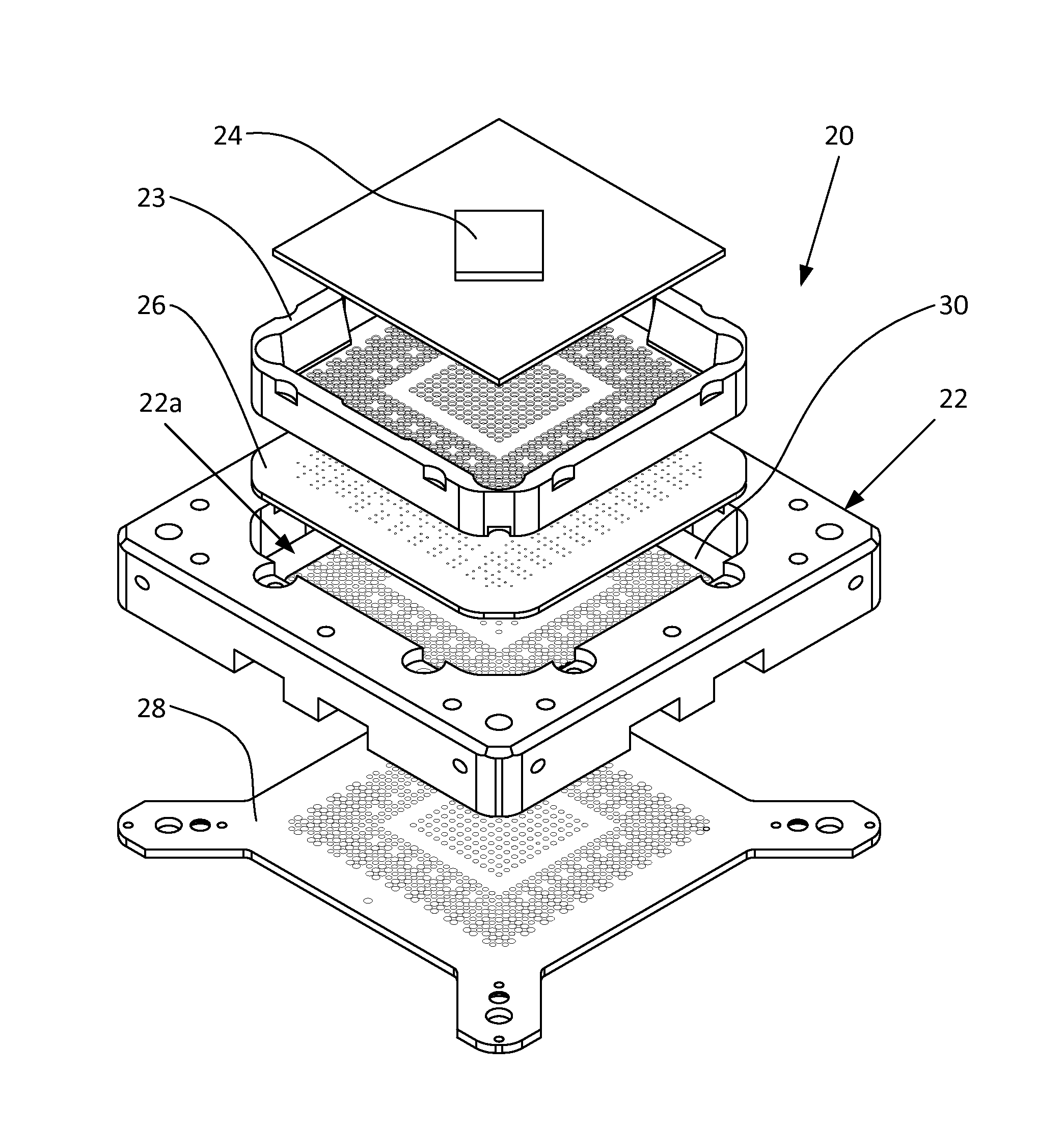
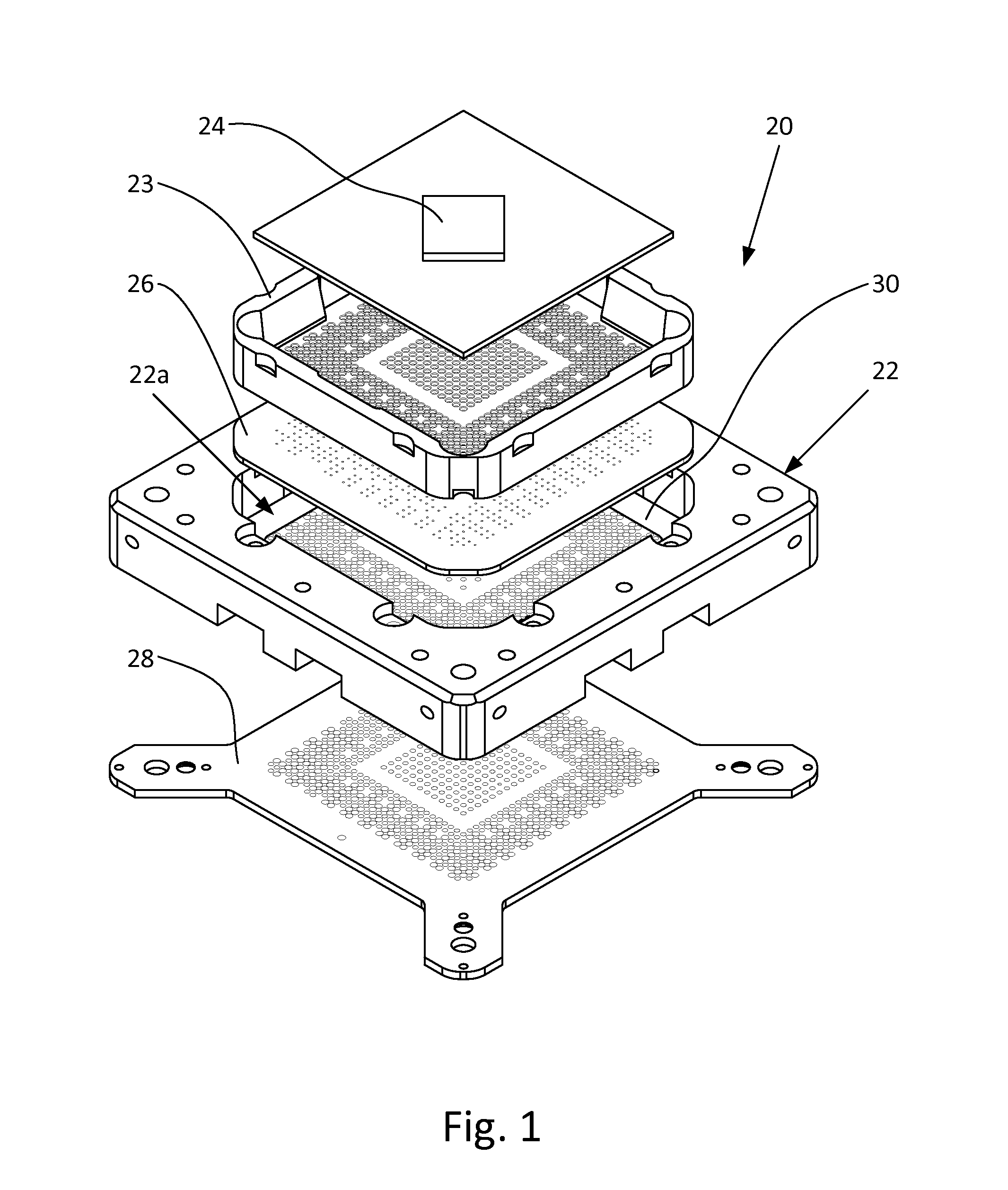
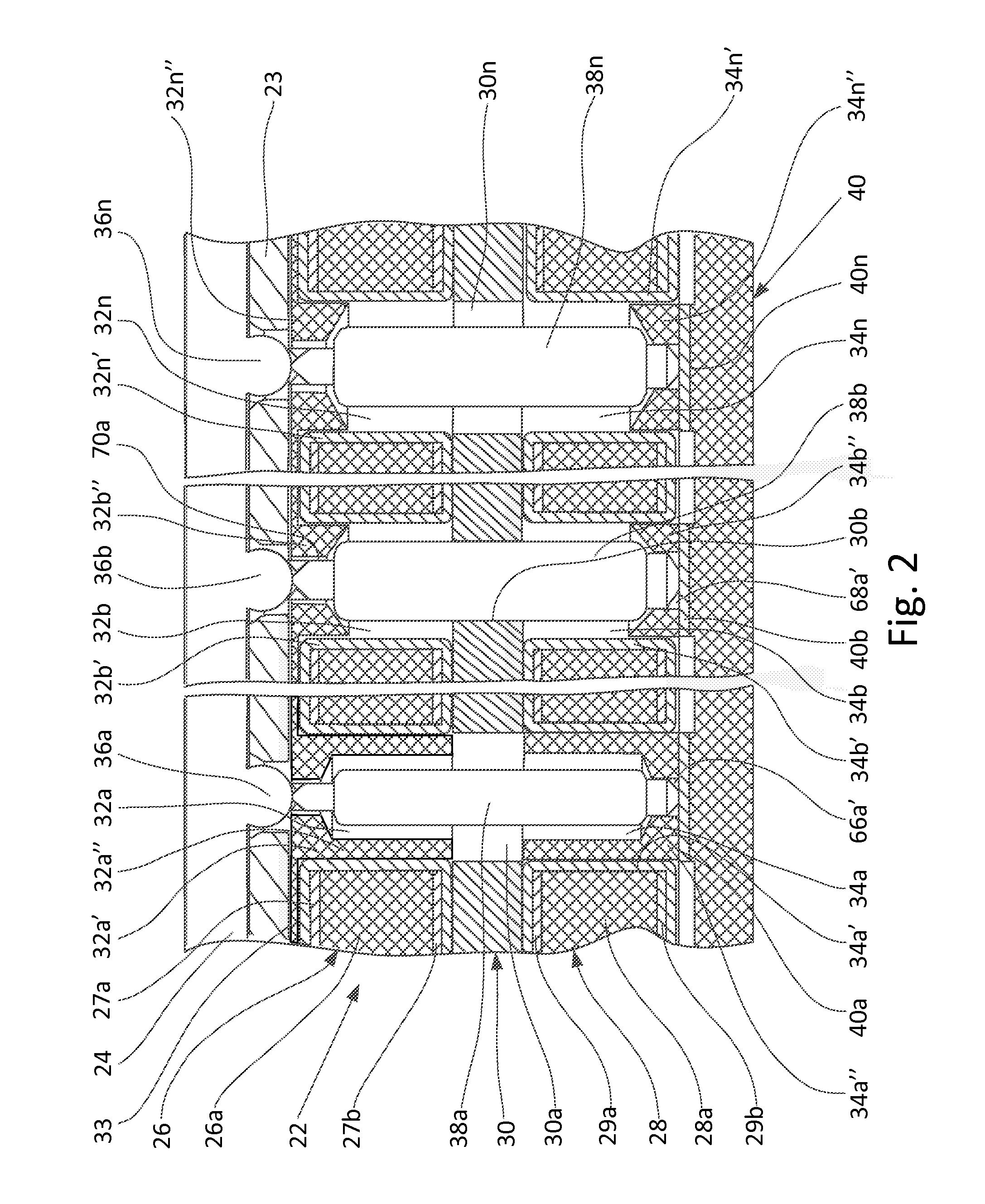
[0029]Since the method of the invention relates to manufacturing of a test socket body of an impedance-matched test socket having a specific structure shown in FIGS. 1 and 2, it will be advantageous first to consider the structure of the test socket body itself.

[0030]A test socket for the manufacture of which the method of the invention is intended is shown in FIG. 1, which is an exploded perspective view of the test socket. It can be seen that the test socket, which in general is designated by reference numeral 20, comprises a test socket body 22, which, is described below with reference to FIG. 2, and comprises a metallic probe holder 30 sandwiched between two laminated probe retainers, i.e., the upper probe retainer 26 and a lower probe retainer 28. FIG. 2 is part of a sectional view through the test socket of the present invention in an assembled state.

[0031]The test socket body 22 has a recess 22a inserted into the upper probe retainer 26 and the lower probe retainer 28. The up...


PUM

PropertyMeasurementUnit
impedance dielectric constantaaaaaaaaaa
inner diametersaaaaaaaaaa
outer diametersaaaaaaaaaa

Abstract

Proposed is a method for manufacturing a coaxial impedance-matched test socket having a socket body with a structure similar to a system of redistributed coaxial cable inserts, where the core of each insert comprises a pogo pin, a metal layer that surrounds the pogo pin functions as a shielding element of the core, and an air gap and an insulation filling between the pogo pin and the shielding metal part function as an isolator. A unique feature of the method consists of employing standard and commercially available parts the use of which significantly decreases the number of manufacturing steps and simplifies the manufacturing process. In addition, the process involves operations that provide simultaneous multiposition treatment which accelerates production.

Description

FIELD OF THE INVENTION[0001]The present invention relates to the field of testing electrical contacts in electrical and electronic devices, in particular to a method of manufacturing of the test socket body of an impedance-matched test socket used, e.g., in operations of final high speed testing (FHST). More specifically, the invention provides a method for manufacturing the test socket body of an FHST socket that eliminates crosstalk, creates impedance-controlled signals of different values on the same socket, and at the same time makes it possible to manufacture the mentioned sockets less expensively than by traditional CNC (computer numerical control) machining by using printed circuit board technology.BACKGROUND OF THE INVENTION[0002]In general, when a process of manufacturing a semiconductor chip such as an integrated circuit (IC) or the like is ended, an electric performance, quality, etc., of the semiconductor chip are tested. In general, when the process of manufacturing a s...

Claims


Application Information

Patent Timeline
Patent Type & Authority Applications(United States)
IPC IPC(8): G01R3/00G01R1/04
CPCG01R1/0441G01R3/00G01R1/07371G01R1/0466Y10T29/49208
Inventor WOODEN, TIMIVANKOV, SERGEY
Owner WOODEN TIM
Learn More