Total harmonic current distortion control circuit and method thereof

a control circuit and total harmonic current technology, applied in the direction of power conversion systems, climate sustainability, efficient power electronics conversion, etc., can solve the problems of increasing the relative cost and complexity of implementing the power factor correction circuit, more damage to the power grid and the back-end equipment, and the inability to achieve the effect of enhancing the convenience of thdi control circuits

Active Publication Date: 2015-08-20
VOLTRONIC POWER TECH CORP
View PDF3 Cites 18 Cited by
  • Summary
  • Abstract
  • Description
  • Claims
  • Application Information

AI Technical Summary

Benefits of technology

[0013]Additionally, the second control unit is operable to output a control voltage to the adjustment unit according to a second adjustment signal of the adjustment unit to control the voltage variation of a line to neutral voltage along with variation in an AC power supplied from the AC power source 8 to the power factor correction circuit to be withi

Problems solved by technology

The higher the THDi is indicating the higher the distortion level, hence more damage to the power grid and the back-end equipment.
Currently, there are many limitations to the performance of power factor correction circuits for small-capacity UPS applic

Method used


Image

  • Total harmonic current distortion control circuit and method thereof
  • Total harmonic current distortion control circuit and method thereof
  • Total harmonic current distortion control circuit and method thereof

Examples


first exemplary embodiment

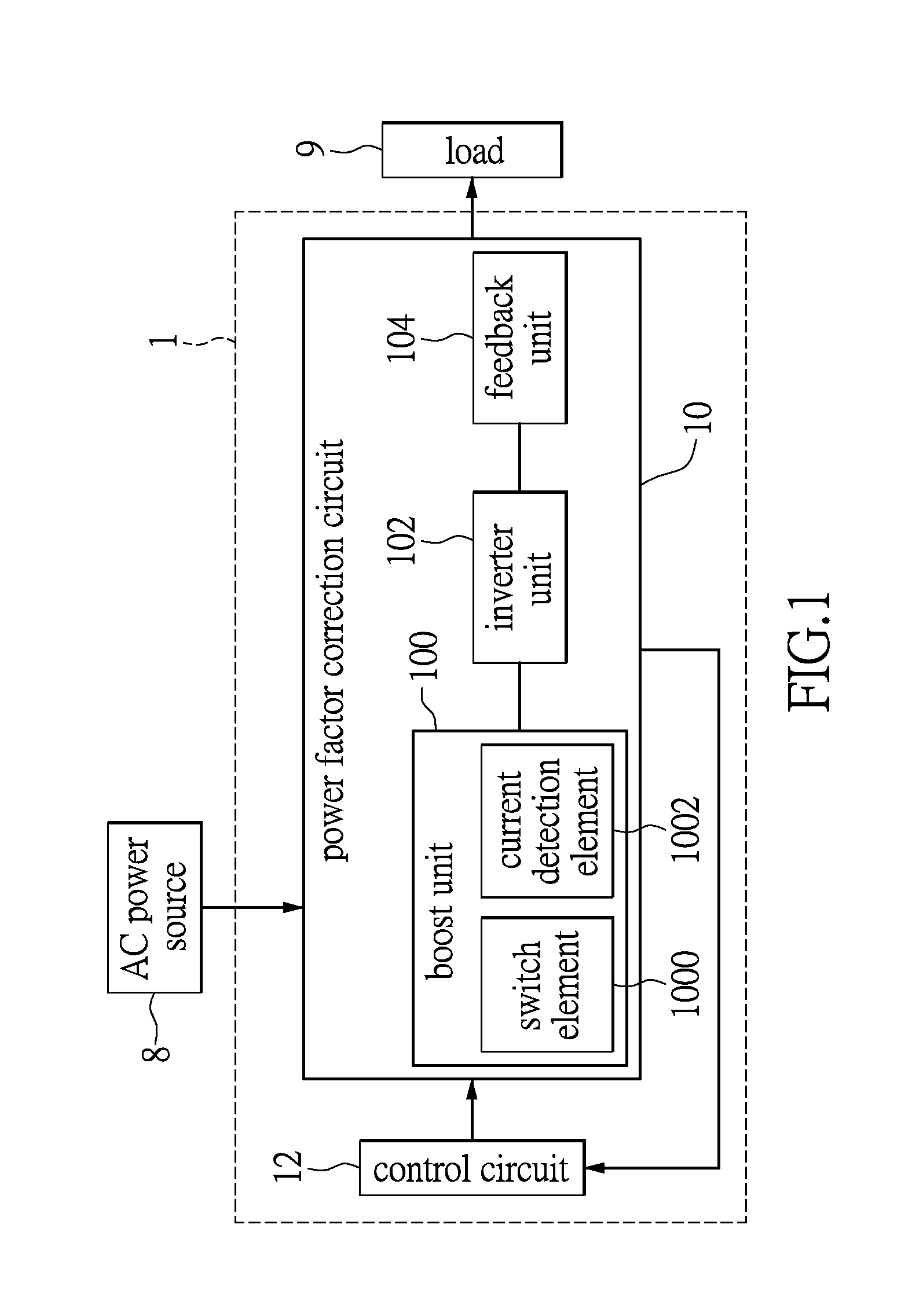
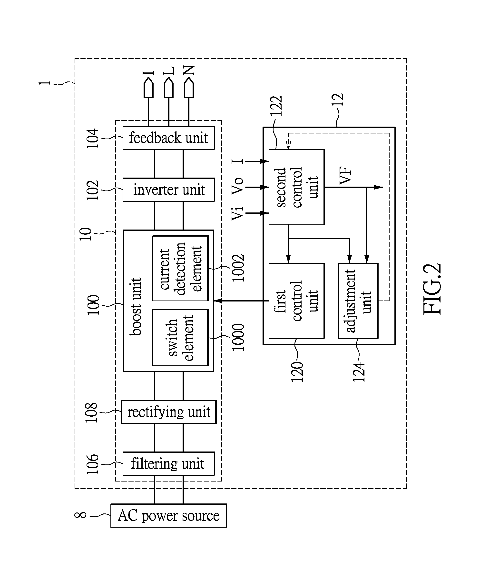
[0030]Please refer to FIG. 1, which shows a block diagram illustrating a total harmonic current distortion (THDi) control circuit provided in accordance with a first exemplary embodiment of the present disclosure. In the present disclosure, a THDi control circuit 1 can be used in an Uninterruptible Power Supply system (UPS) application for controlling the total harmonic current distortion. The THDi control circuit 1 includes a power factor correction circuit 10 and a control circuit 12. The control circuit 12 is coupled to the power factor correction circuit 10. The power factor correction circuit 10 is coupled to an AC power source 8, a load 9, and the control circuit 12. The control circuit 12 operatively controls a power factor and the THDi of the power factor correction circuit 10 according to an output power of the power factor correction circuit 10 and an input current supplied to the power factor correction circuit 10, so that the power factor of the power factor correction c...

second exemplary embodiment

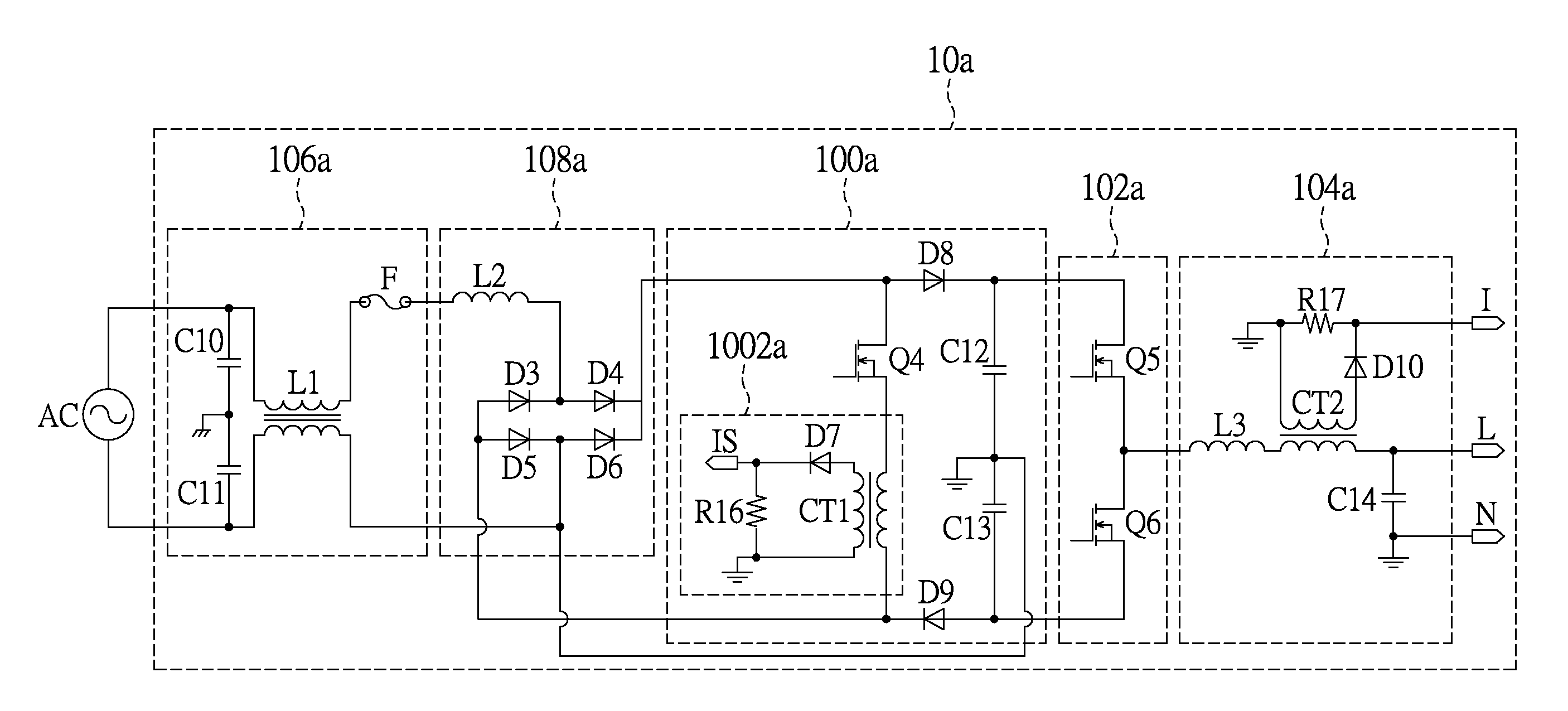
[0051]Please refer to FIG. 3A, which shows a schematic diagram illustrating a power factor correction circuit of a THDi control circuit provided in accordance with a second exemplary embodiment of the present disclosure. A power factor correction circuit 10a is electrically connected to an AC power source to receive an AC power input. The power factor correction circuit 10a includes a filtering unit 106a, a rectifying unit 108a, a boost unit 100a, an inverter unit 102a, and a feedback unit 104a. An AC power source is coupled to the filtering unit 106a. The rectifying unit 108a is coupled to the filtering unit 106a and the boost unit 100a. The inverter unit 102a is coupled to the boost unit 100a and the feedback unit 104a.

[0052]The filtering unit 106a comprises of two filter capacitors C10, C11 and a common-mode inductor L1. The filter capacitor C10 and the filter capacitor C11 are designed to have same capacitance. The two filter capacitors C10, C11 are coupled between the AC power...

third exemplary embodiment

[0059]Please refer to FIG. 5 and FIG. 3A. FIG. 5 shows a schematic diagram illustrating an adjustment unit of a THDi control circuit provided in accordance with a third exemplary embodiment of the present disclosure. The adjustment unit 124a can be implemented by a processing chip 1240 and various electrical components including a plurality of capacitors C1 to C9, a plurality of resistors R1 to R15, RS and a plurality of bipolar junction transistors (BJT) Q1˜Q3. The processing chip 1240a has a plurality of pins. An I / S pin is configured to receive the aforementioned sensing current IS and the PWM signal. A VF pin is configured to receive a control voltage VF. The circuitry for detecting the control voltage VF and the circuitry for detecting the sensing current IS are two independent and separated closed loops such that the control voltage VF and the sensing current IS can be individually detected, thereby increases the current and voltage detection accuracy. A Com pin is configured ...


PUM


Abstract

A total harmonic current distortion (THDi) control circuit includes a power factor correction circuit and a control circuit. The power factor correction circuit includes a boost unit, an inverter unit, and a feedback unit. The boost unit includes a switch element and a current detection element series-coupled to the switch element. The feedback unit operatively detects an output voltage and an output current of the power factor correction circuit. The control circuit calculates an output power according to the output voltage and the output current, and calculates an input voltage and an input current according to the output power. The control circuit outputs a pulse width modulation signal and controls a conduction current generated by the switch element according to the input current. The control circuit adjusts the duty cycle of the pulse width modulation signal according to the conduction current detected by the current detection element.

Description

BACKGROUND[0001]1. Technical Field[0002]The present disclosure relates to a circuit and a method for controlling a total harmonic current distortion (THDi), in particular, to a THDi control circuit and method thereof.[0003]2. Description of Related Art[0004]A power factor (PF) represents the relationship between the effective or the real power and the apparent power. In other words, the power factor is defined as the ratio of the effective power to the apparent power. Basically, a power factor can be used to measure how efficient the electricity is being used. The larger the power factor is, the more efficiently the electricity is used.[0005]A total harmonic current distortion (THDi) represents a distortion level of the current returning to the power grid. The higher the THDi is indicating the higher the distortion level, hence more damage to the power grid and the back-end equipment. High performance equipment generally has the range of the THDi clearly defined. Therefore, the THDi...

Claims


Application Information

Patent Timeline
IPC IPC(8): H02M1/42H02M7/537
CPCH02M7/537H02M1/4208H02M1/12H02M1/4225H02M7/53875Y02B70/10
Inventor CHEN, MING HSIENHU, BINHSIEH, JUOR-MING
Owner VOLTRONIC POWER TECH CORP
Why Eureka
Try Eureka