Synchronization signal transmitting device, method thereof and power electronic apparatus having the device

a technology of synchronization signal and transmitting method, which is applied in the direction of power distribution line transmission, multiplex communication, generating/distributing signals, etc., can solve the problems of low time accuracy of information transmission, difficulty in reliably transmitting synchronization signal among multiple power electronic apparatuses, and high necessary baud rate, etc., to achieve low time delay and high time accuracy

Active Publication Date: 2015-08-20
DELTA ELECTRONICS (SHANGHAI) CO LTD
View PDF8 Cites 29 Cited by
  • Summary
  • Abstract
  • Description
  • Claims
  • Application Information

AI Technical Summary

Benefits of technology

[0014]The primary objective of the present invention is to provide a synchronization signal transmitting device and a method thereof, wherein the synchronization signal transmitting device and the method reveal the important technology features of simplicity in architecture and adjustment of time delay compensation. Moreover, the device and method also show the following advantages: transmission and process purely by hardware without participation of software, without occupation to calculating ability of processors, high time accuracy, and low time delay. The proposed synchronization signal transmitting device is able to assure the reliability of synchronization signal transmission in a long distance in a power electronic system under a harsh electromagnetic environment.

Problems solved by technology

However, for a broad range-distributed power system, there are often long-distance (several hundred meters far at most) and strong electro-magnetic interference (EMI) among each other of different power electronic apparatuses, which lead to difficulty in reliably transmitting synchronization signal among multiple power electronic apparatuses.
(1) The aforesaid method may be used for transmitting the low frequency clock information such as power frequency of 50 Hz or 60 Hz, but cannot be used for transmitting high frequency PWM carrier clock information. The reason is that the Baud Rate used in the aforesaid method must be dozens times as high as the frequency of the transmitted synchronization clock information. Therefore, the necessary Baud Rate would be extremely high if the aforesaid method is used for transmitting the PWM carrier clock information (from several kHz to hundreds of kHz). For instance, when the PWM carrier has a frequency of 100 kHz, the necessary Baud Rate to transmit the data frame must be at least 5 Mbps. However, the CAN bus and / or the RS-485 bus are unable to accomplish such information transmission especially under a harsh electromagnetic environment in a long distance.
(2) The information transmission has very low time accuracy in the aforesaid method. In addition to receiving the synchronous clock signal, the processor at the receiver has many other programs to execute, for example, the high-priority interrupt program, the execution of which may affect the operation time of decoding and checking of the data frame. This would reduce the time accuracy of the transmitted synchronization clock information.
(3) The aforesaid method has a complicated adjustment of time delay compensation. From the aforesaid point (2), it may be known that a time delay of several milliseconds to hundreds of milliseconds may be caused due to execution of other programs. For this reason, the processor must make time delay compensation to the synchronization information. However, the execution time of software varies with the change of program code, which is not a constant, and this increases the difficulty and complicity in making time delay compensation to the synchronization signal.
(4) The aforesaid method has a high occupation to operating ability of the processors. From aforesaid points (2) and (3), in the aforesaid method the decoding, checking and time delay compensation of the data frame is mainly done by software, and thereby extracting the synchronization signal. However, with the frequency of the synchronization clock information increasing, the execution time of the used software become more inconstant, and hence a processor with higher operating ability is required, which leads to increased cost in processors.

Method used


Image

  • Synchronization signal transmitting device, method thereof and power electronic apparatus having the device
  • Synchronization signal transmitting device, method thereof and power electronic apparatus having the device
  • Synchronization signal transmitting device, method thereof and power electronic apparatus having the device

Examples


Embodiment Construction

[0035]To more clearly describe a synchronization signal transmitting device, a synchronization signal transmitting method and a power electronic apparatus having the synchronization signal transmitting device according to the present invention, embodiments of the present invention will be described in detail with reference to the attached drawings hereinafter.

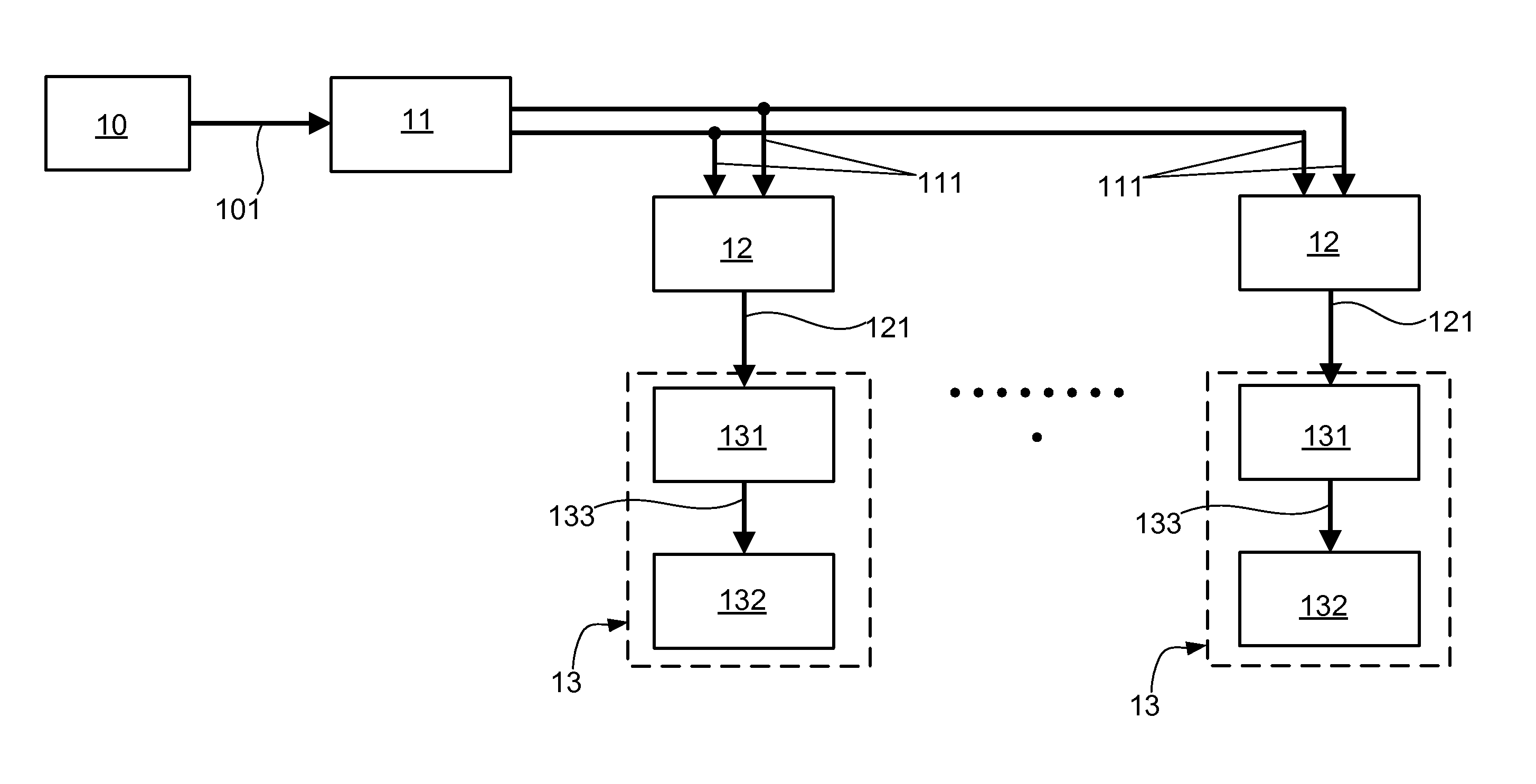
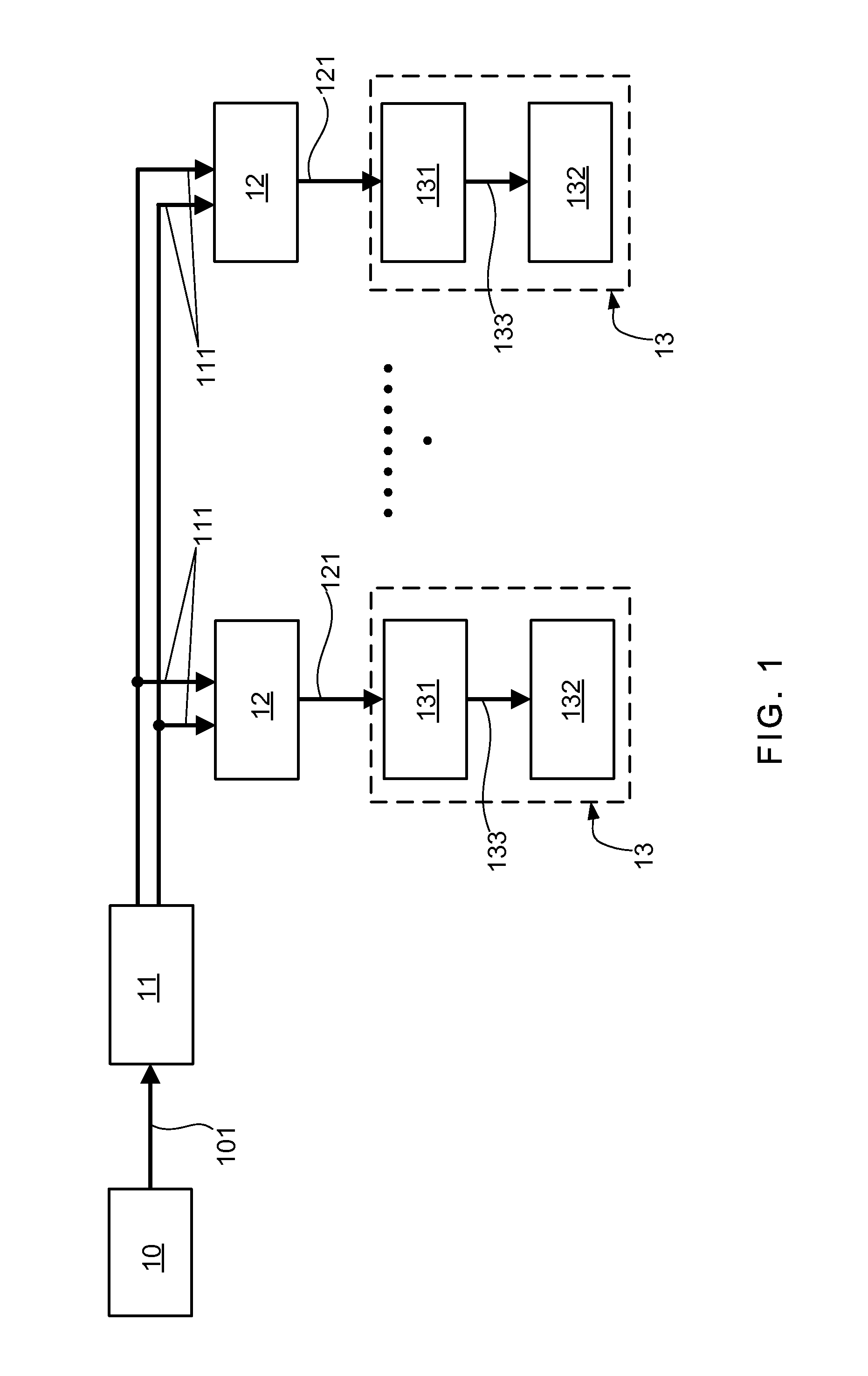
[0036]With reference to FIG. 1, which illustrate an architecture diagram of a synchronization signal transmitting device according to the present invention. As shown in FIG. 1, the synchronization signal transmitting device of the present invention consists of: at least one serial differential signal transmitter 11, at least one serial differential signal receiver 12 and at least one controller 13 (FIG. 1 shows N serial differential signal receivers 12 and N controllers 13). In the present invention, the serial differential signal transmitter 11 is coupled to a synchronization signal transmitting unit 10 for receiving an identi...


PUM


Abstract

The present invention relates to a synchronization signal transmitting device, method thereof and a power electronic apparatus with the device. The synchronization signal transmitting device comprises at least one serial differential signal transmitter for receiving an identical-period pulse signal and outputting a differential signal pair, at least one serial differential signal receiver for receiving the differential signal pair and outputting a single-ended signal, and at least one controller for receiving the single-ended signal. Moreover, the controller is configured for conducting a signal filtering process and / or a signal reconstruction process to the single-ended signal, so as to obtain a synchronization signal. Thus, the present invention shows the advantages of transmission and process purely by hardware without participation of software, without occupation to calculating ability of processors, high time accuracy, and low time delay. The method and device can not only transmitting the identical synchronous clock signal with power frequency, but also the PWM carrier synchronous clock signal with high frequency ranged from several kHz to hundreds kHz.

Description

BACKGROUND OF THE INVENTION[0001]1. Field of the Invention[0002]The present invention relates to the technology field of power electronic apparatuses, and more particularly to a synchronization signal transmitting device, a synchronization signal transmitting method and a power electronic apparatuses having the device.[0003]2. Description of the Prior Art[0004]In controlling a power electronic system, an identical synchronization clock signal with power frequency (called “power-frequency clock information” hereinafter) and / or a PWM carrier synchronization clock information (called “PWM carrier clock information” hereinafter) are provided to multi paralleled power electronic apparatuses so as to coordinate these apparatuses and enhance the electric power quality outputted by these apparatuses. Moreover, in the conventional power electronic system, an active detection method is commonly used for islanding detection in each of the power electronic apparatuses. To ensure the disturbance...

Claims


Application Information

Patent Timeline
Patent Type & Authority Applications(United States)
IPC IPC(8): H04L7/00G06F1/26
CPCG06F1/26H04L7/0008H04L25/0272H04L25/4902G06F1/04G06F1/12H04B3/54H04J3/06H04L7/00
Inventor PAN, QIELUGUAN, WEIWU, HONGYANG
Owner DELTA ELECTRONICS (SHANGHAI) CO LTD
Why Eureka
Try Eureka