Method of forming an abradable coating for a gas turbine engine

a gas turbine engine and abradable coating technology, applied in the direction of inorganic powder coating, leakage prevention, liquid spraying apparatus, etc., can solve the problems of reducing the density of particles, reducing the spacing of interparticles, and reducing the effect of lubricant properties

Inactive Publication Date: 2015-08-27
PRATT & WHITNEY CANADA CORP
View PDF5 Cites 7 Cited by
  • Summary
  • Abstract
  • Description
  • Claims
  • Application Information

AI Technical Summary

Benefits of technology

[0003]In one aspect is provided a method of forming an abradable coating on a gas turbine engine component, the method comprising, in sequence: placing dry lubricant particles and trapping particles in a channel having a spraying end and containing a gas; causing at least one shockwave in the gas to travel in the channel toward the spraying end, the at least one shockwave causing the dry lubricant particles and the trapping particles to travel in the channel with it, the at least one shockwave reducing interparticle spacing and increasing particles density; directing a resulting flow of the dry lubricant particles and the trapping particles from the spraying end at a supersonic velocity to impact the component; and then plastically deforming the trapping particles upon impacting the component with the resulting flow thereby trapping the dry lubricant particles with the deformed trapping particles onto the component to provide the abradable coating.

Problems solved by technology

In such cases, the casing has an abrabable coating that will wear upon contact with the blade tips.
If using conventional cold spray coating, the high speed imparted to the dry lubricant particles may cause the dry lubricant particles to shatter upon impact with the component.
If using plasma spray, the high temperature decomposes the dry lubricant particles, which may lose their dry lubricant properties.

Method used


Image

  • Method of forming an abradable coating for a gas turbine engine
  • Method of forming an abradable coating for a gas turbine engine
  • Method of forming an abradable coating for a gas turbine engine

Examples


Embodiment Construction

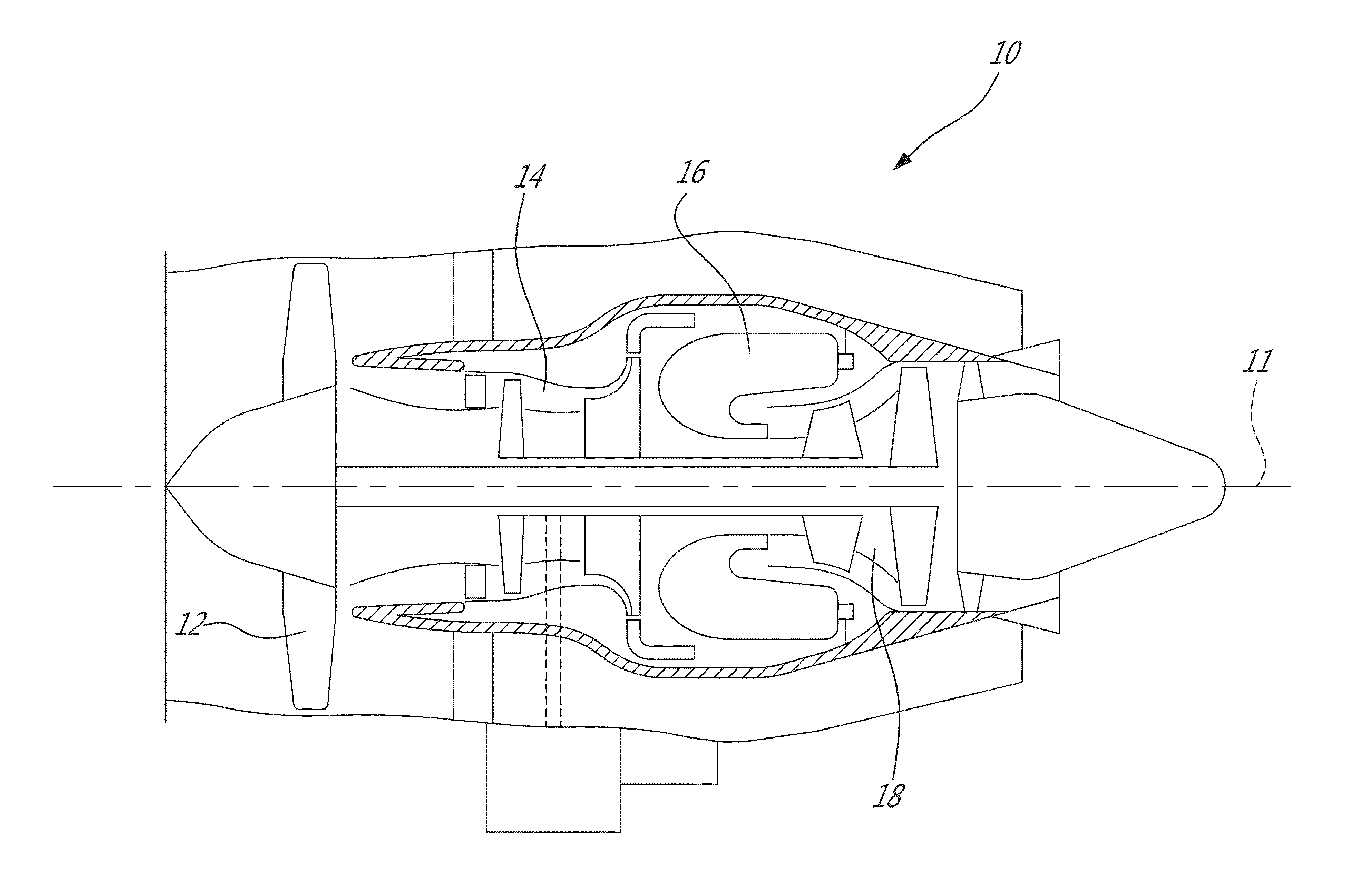
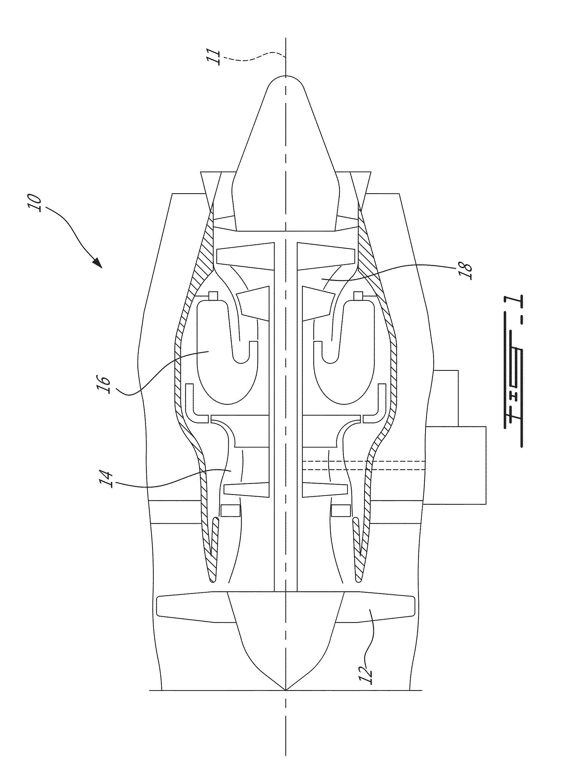
[0011]FIG. 1 illustrates a gas turbine engine 10 of a type preferably provided for use in subsonic flight, generally comprising in serial flow communication a fan 12 through which ambient air is propelled, a compressor section 14 for pressurizing the air, a combustor 16 in which the compressed air is mixed with fuel and ignited for generating an annular stream of hot combustion gases, and a turbine section 18 for extracting energy from the combustion gases. Some components of the engine 10 have abradable surfaces that may be formed by coating dry lubricant thereonto.

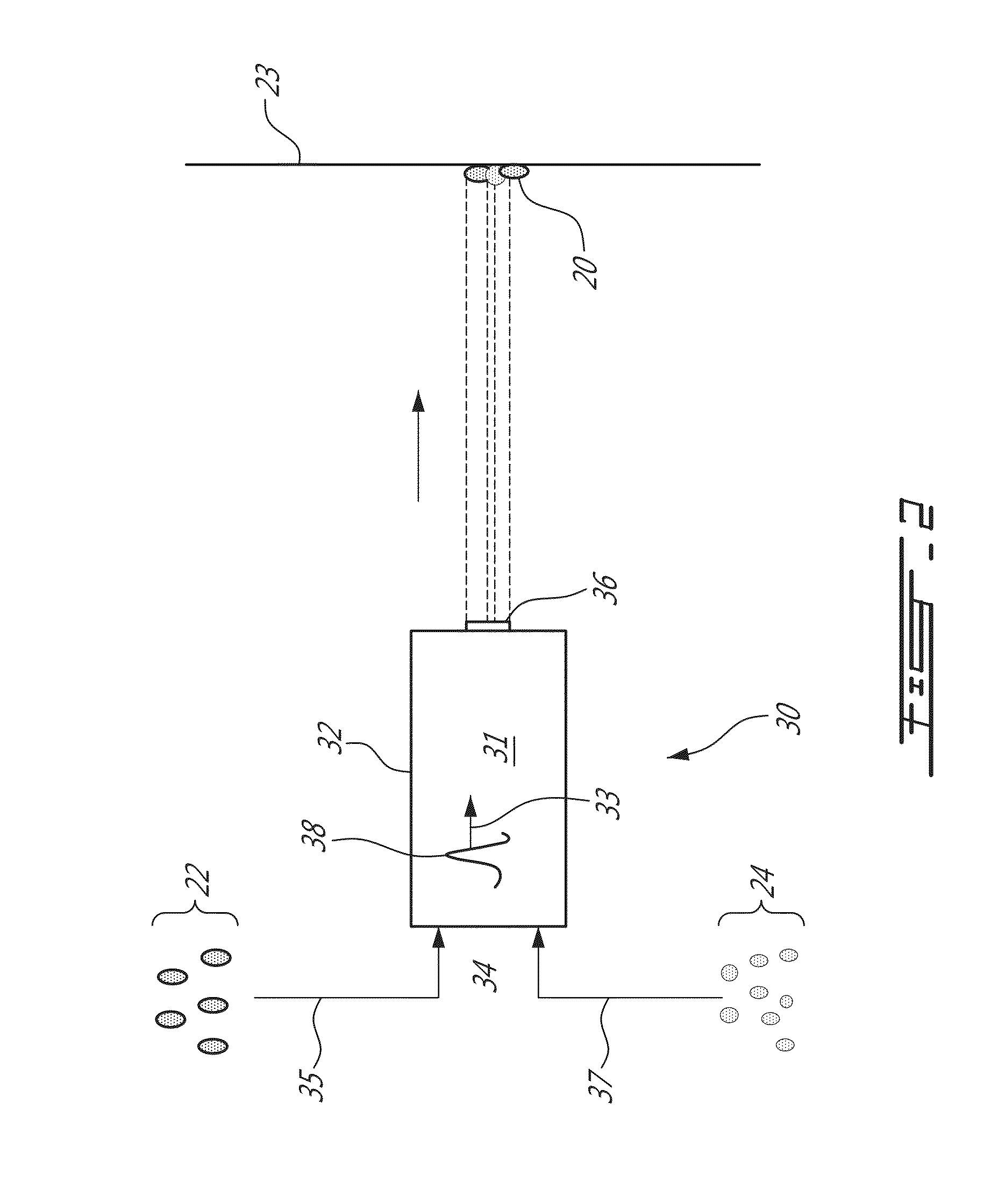
[0012]Referring to FIG. 2, an abradable coating 20 is made by bonding dry lubricant particles 22 onto a component 23 using projected trapping particles 24. The trapping particles 24 trap the dry lubricant particles 22 as they impact the component 23. The component 23 could be made of any suitable material for the desired application. For example, it could be a metal, an alloy or a polymer composite.

[0013]A shockwave gene...


PUM

PropertyMeasurementUnit
lengthaaaaaaaaaa
temperatureaaaaaaaaaa
pressureaaaaaaaaaa

Abstract

A method of forming an abradable coating on a gas turbine engine component comprising, in sequence: placing dry lubricant particles and trapping particles in a channel having a spraying end and containing a gas; causing at least one shockwave in the gas to travel in the channel toward the spraying end, the at least one shockwave causing the dry lubricant particles and the trapping particles to travel in the channel with it, the at least one shockwave reducing interparticle spacing and increasing particles density; directing a resulting flow of the dry lubricant particles and the trapping particles from the spraying end at a supersonic velocity to impact the component; and then plastically deforming the trapping particles upon impacting the component with the resulting flow thereby trapping the dry lubricant particles with the deformed trapping particles onto the component to provide the abradable coating.

Description

TECHNICAL FIELD[0001]The application relates generally to abradable coatings in gas turbine engine components and more specifically to methods of forming abradable coatings.BACKGROUND OF THE ART[0002]Abradable surfaces are commonly found in gas turbine engines, for instance where a minimal clearance is needed (e.g., between blade tips and casing). In such cases, the casing has an abrabable coating that will wear upon contact with the blade tips. To form an abradable coating, dry lubricant particles are coated onto a component. If using conventional cold spray coating, the high speed imparted to the dry lubricant particles may cause the dry lubricant particles to shatter upon impact with the component. In turn, the dry lubricant particles do not adhere to the component. If using plasma spray, the high temperature decomposes the dry lubricant particles, which may lose their dry lubricant properties.SUMMARY[0003]In one aspect is provided a method of forming an abradable coating on a ga...

Claims


Application Information

Patent Timeline
Patent Type & Authority Applications(United States)
IPC IPC(8): B05D5/00
CPCB05D5/00F01D11/122C23C24/04B05B7/1486
Inventor CHEUNG, KIN-LEUNG
Owner PRATT & WHITNEY CANADA CORP
Why Eureka
Try Eureka