Light source device and projection device

a technology of projection device and light source device, which is applied in the direction of instruments, lighting and heating apparatus, fibre light guides, etc., can solve the problems of reducing reducing the accuracy of coupling length adjustment, and matching each wavelength, so as to enhance the efficiency of light utilization

Active Publication Date: 2015-08-27
CITIZEN WATCH CO LTD
View PDF1 Cites 66 Cited by
  • Summary
  • Abstract
  • Description
  • Claims
  • Application Information

AI Technical Summary

Benefits of technology

[0013]In view of the above, it is an object of the present invention to provide a light source device having optical fiber arrays arranged so that different sets of RGB laser lights are focused at different depth positions, while enhancing the efficiency of light utilization. It is also an object of the present invention to provide a projection device that can project multicolored images onto different depth positions.
[0022]According to the above light source device, different sets of RGB laser lights can be focused at different depth positions, while enhancing the efficiency of light utilization, by bundling together the optical fibers with the fiber bundle combiner. According to the above projection device, multicolored images can be projected onto different depth positions.

Problems solved by technology

However, when the fused fiber combiner is used, since the coupling length over which the laser light is coupled from one waveguide to another waveguide with high efficiency is different for each wavelength, it is difficult to accurately adjust the coupling length so as to match each wavelength.
As a result, crosstalk, etc., may occur between adjacent cores, reducing the efficiency of light utilization.

Method used


Image

  • Light source device and projection device
  • Light source device and projection device
  • Light source device and projection device

Examples


Embodiment Construction

[0039]Hereinafter, with reference to the accompanying drawings, a light source device and a projection device will be explained in detail. However, it should be noted that the technical scope of the present invention is not limited to embodiments thereof, and includes the invention described in claims and equivalents thereof.

[0040]An eyeglass-type volumetric display will be described below as an example of a projection device that uses a light source device as a light source unit. However, the projection device is not limited to the eyeglass type, the only requirement being that it be a volumetric display that projects a stereoscopic image by focusing different sets of RGB laser lights onto different depth positions.

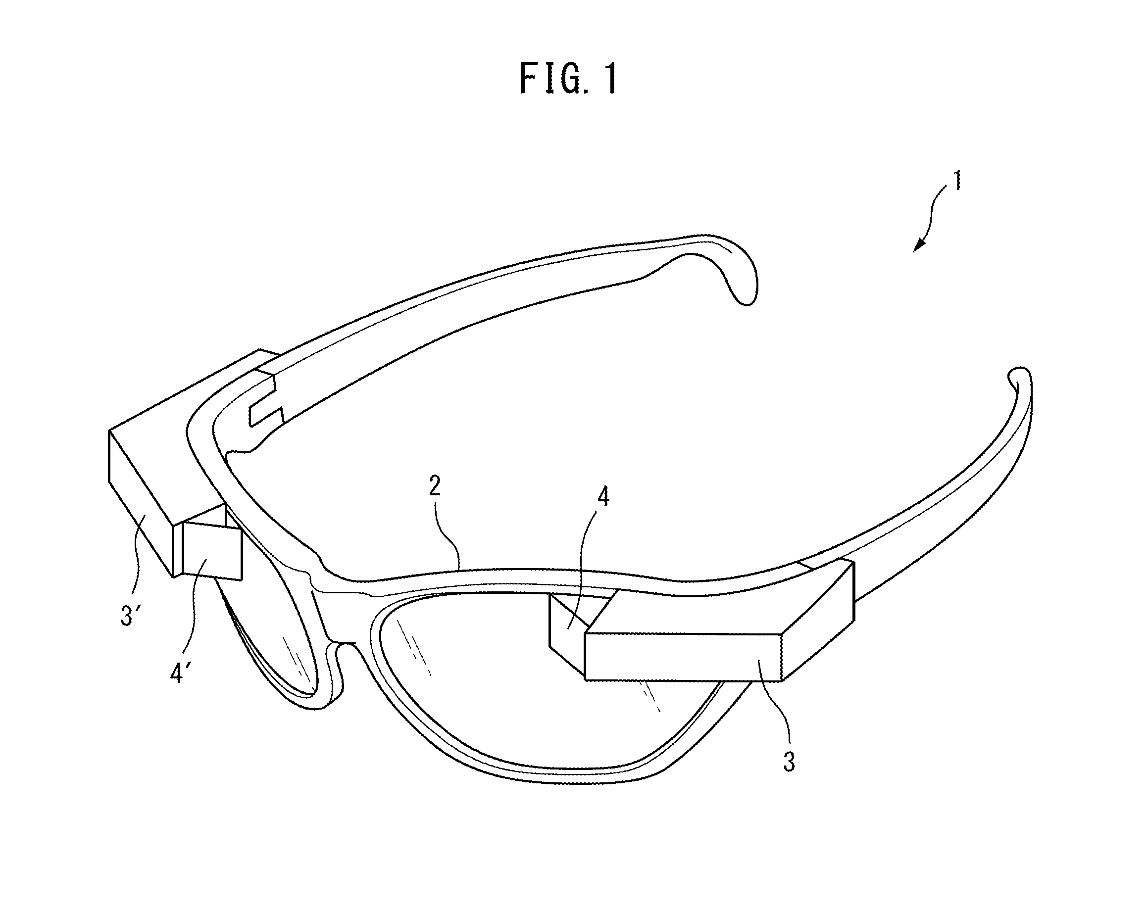
[0041]FIG. 1 is a perspective view of an eyeglass-type volumetric display 1. The volumetric display 1 is a near-to-eye (NTE) display which is mounted on the head of a user and which presents an image for viewing by projecting laser light onto the retina of the user's eye...


PUM


Abstract

Provided is a light source device having optical fiber arrays arranged so that different sets of RGB laser lights are focused at different depth positions, while enhancing the efficiency of light utilization. The light source device includes a plurality of optical devices each of which generate red, green, or blue laser light, a plurality of first, second, and third optical fibers through each of which the red, green, or blue laser light from a corresponding one of the plurality of optical devices is guided, and a fiber bundle combiner which forms a fiber bundle by fixedly holding together end portions of the plurality of first, second, and third optical fibers in such a manner that a plurality of optical fiber sets, each comprising three optical fibers one from the first optical fibers, one from the second optical fibers, and one from the third optical fibers, are stacked in layers.

Description

TECHNICAL FIELD[0001]The present invention relates to a light source device and a projection device.BACKGROUND ART[0002]An image display device is known that displays an image in a stereoscopic fashion. For example, patent document 1 discloses an image display device which includes a plurality of transparent fibers arranged in a two-dimensional matrix pattern, the length of each fiber being changed at the display end for each individual pixel which is the smallest unit forming a display screen, and light sources arranged uniformly behind the respective fibers. This image display device provides a sense of depth to the displayed image by changing the length of each fiber in a stepwise manner at the display end and thereby creating relative differences in height at the top ends of the respective fibers.[0003]A three-dimensional display device for displaying a stereoscopic image, called a volumetric display, is also known (for example, refer to patent document 2). The volumetric displa...

Claims


Application Information

Patent Timeline
Patent Type & Authority Applications(United States)
IPC IPC(8): F21V8/00G02B27/01G02B27/22G02B26/08
CPCG02B6/0005G02B27/22G02B27/0172G02B26/0833G02B6/0008G02B6/08G02B6/30G02B6/3822G02B6/40G02B6/4249G02B27/017G02B2027/015G02B2027/0178G02B30/50G02B6/00
Inventor IDE, MASAFUMIFUKAYA, SHINPEIYODA, KAORU
Owner CITIZEN WATCH CO LTD
Why Eureka
Try Eureka