Liquid discharging apparatus, head unit, and control method of liquid discharging apparatus

a liquid discharging apparatus and liquid discharging head technology, applied in the direction of electronic switching, pulse technique, printing, etc., can solve the problems of increased loss due to switching, large electric power consumption, poor energy efficiency,

Active Publication Date: 2015-09-03
SEIKO EPSON CORP
View PDF4 Cites 25 Cited by
  • Summary
  • Abstract
  • Description
  • Claims
  • Application Information

AI Technical Summary

Benefits of technology

[0012]An advantage of some aspects of the invention is that, in a configuration in which a piezoelectric element is driven by a drive signal subjected to class D amplification, a liquid discharging apparatus capable of performing high-speed printing and high-resolution printing, a head unit, and a control method of the liquid discharging apparatus are provided.

Problems solved by technology

However, in the case of linear amplification, electric power consumption is large and energy efficiency is not good.
However, when the switching frequency is increased, the loss due to switching is increased.
As a result, it is not possible to ensure high energy efficiency which is an advantage of the class D amplification.
Furthermore, when switching in class D amplification is performed at high frequency, a problem, such as an operational failure due to noise and a heat generation due to switching loss, can occur.

Method used


Image

  • Liquid discharging apparatus, head unit, and control method of liquid discharging apparatus
  • Liquid discharging apparatus, head unit, and control method of liquid discharging apparatus
  • Liquid discharging apparatus, head unit, and control method of liquid discharging apparatus

Examples


Embodiment Construction

[0055]Hereinafter, an embodiment of the invention will be described with reference to the accompanying drawings.

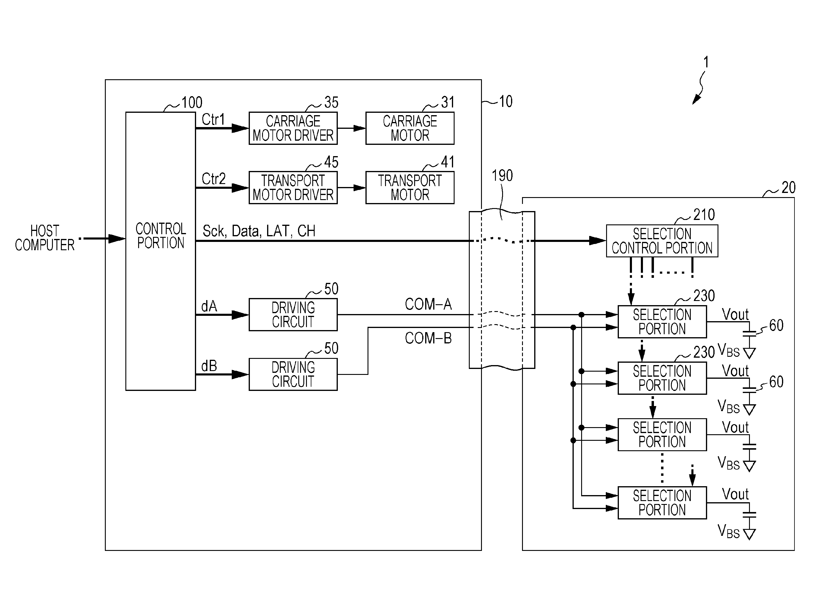
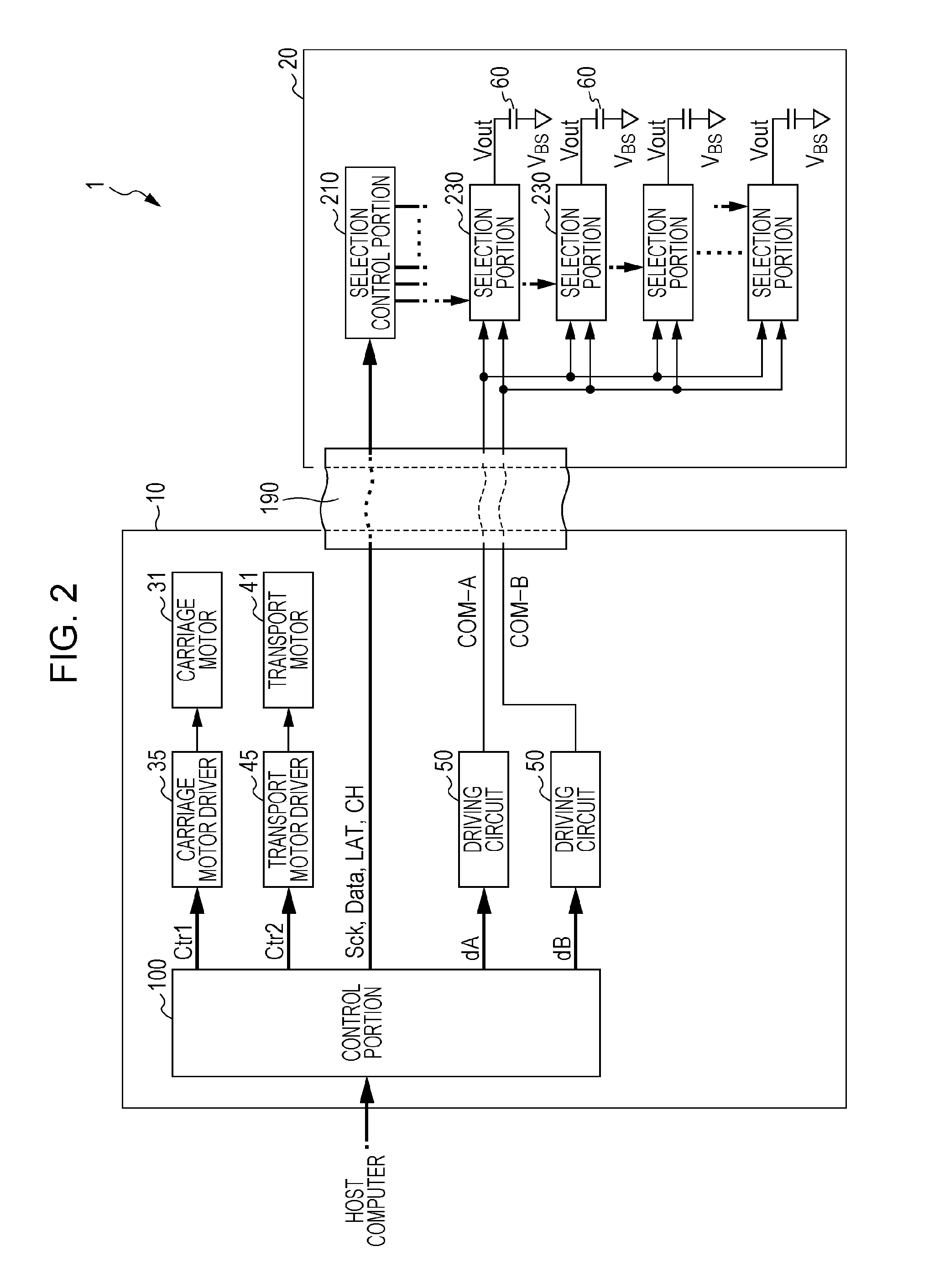
[0056]A printing apparatus according to this embodiment is an ink jet printer, in other words, a liquid discharging apparatus, in which ink is discharged in accordance with image data supplied from an external host computer and a group of ink dots are formed in a printing medium, such as a paper sheet, in such a manner that the image (which includes letters, graphics, and the like) corresponding to the image data is printed.

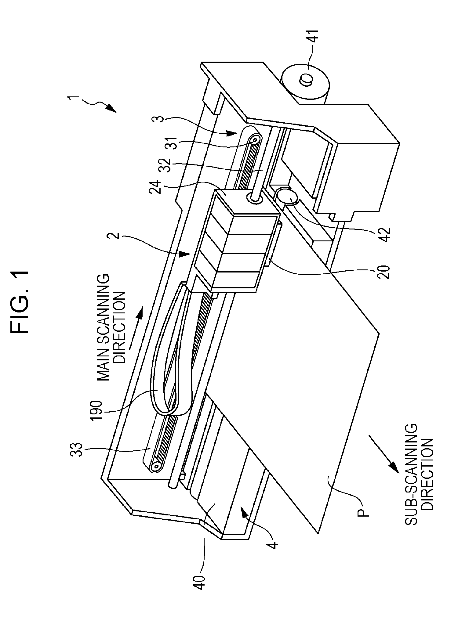
[0057]FIG. 1 is a perspective view illustrating the schematic internal configuration of the printing apparatus.

[0058]A printing apparatus 1 includes a movement mechanism 3 which moves (reciprocates) a movable body 2 in a main scanning direction, as illustrated in FIG. 1.

[0059]The movement mechanism 3 has a carriage motor 31, a carriage guide shaft 32, and a timing belt 33. The carriage motor 31 functions as a drive source of the movable body 2. Both end...


PUM


Abstract

Provided is a liquid discharging apparatus which includes a modulation circuit which generates a modulation signal which is obtained by pulse-modulating a source signal, a transistor which generates an amplified modulation signal by amplifying the modulation signal, a low pass filter which generates a drive signal by smoothening the amplified modulation signal, a piezoelectric element which is displaced by receiving the drive signal, and a circuit substrate on which the transistor is mounted. The transistor includes a first electrode, a second electrode, a third electrode, and a clip which has conductivity, is electrically connected to the first electrode. Furthermore, the circuit substrate has a first land corresponding to the first electrode, a second land corresponding to the second electrode, and a third land corresponding to the third electrode. In addition, a part of the clip is connected to the third land.

Description

[0001]The entire disclosure of Japanese Patent Application No. 2014-040368, filed Mar. 3, 2014 is expressly incorporated by reference herein.BACKGROUND[0002]1. Technical Field[0003]The present invention relates to a liquid discharging apparatus, a head unit, and a control method of the liquid discharging apparatus.[0004]2. Related Art[0005]An ink jet printer having piezoelectric elements has been known as an ink jet printer which prints an image or a document by discharging ink. In a head unit, the piezoelectric elements are provided respectively corresponding to a plurality of nozzles. The respective piezoelectric elements are driven in accordance with drive signals, in such a manner that a predetermined amount of ink (liquid) is discharged from the nozzles at a predetermined time. As a result, dots are formed. In an electrical point of view, the piezoelectric element is a capacitive load, such as a capacitor. Thus, when a piezoelectric element corresponding to each nozzle is opera...

Claims


Application Information

Patent Timeline
Patent Type & Authority Applications(United States)
IPC IPC(8): B41J2/045
CPCB41J2/04581B41J2/04541B41J2/04588B41J2/04593B41J2/04596B41J2002/14491H03K17/687
Inventor ABE, AKIRASUGITA, HIROSHI
Owner SEIKO EPSON CORP
Why Eureka
Try Eureka