Thermal flow sensor, gas sensor comprising at least one such sensor and pirani gauge comprising at least one such sensor

a flow sensor and sensor technology, applied in the field of thermal flow sensors, can solve the problems of increasing the flicker noise, not allowing to completely eliminate the phenomena occurring outside the sensor itself, and reducing the accuracy of the measurement results

Active Publication Date: 2015-09-03
COMMISSARIAT A LENERGIE ATOMIQUE ET AUX ENERGIES ALTERNATIVES
View PDF6 Cites 10 Cited by
  • Summary
  • Abstract
  • Description
  • Claims
  • Application Information

AI Technical Summary

Benefits of technology

[0008]Consequently, one purpose of the present invention is to provide a thermal flow sen...

Problems solved by technology

Such a sensor is of a complex manufacture because it requires making the support plate and then making the heating element.
These sensors have the drawback not to allow to get completel...

Method used


Image

  • Thermal flow sensor, gas sensor comprising at least one such sensor and pirani gauge comprising at least one such sensor
  • Thermal flow sensor, gas sensor comprising at least one such sensor and pirani gauge comprising at least one such sensor
  • Thermal flow sensor, gas sensor comprising at least one such sensor and pirani gauge comprising at least one such sensor

Examples


Embodiment Construction

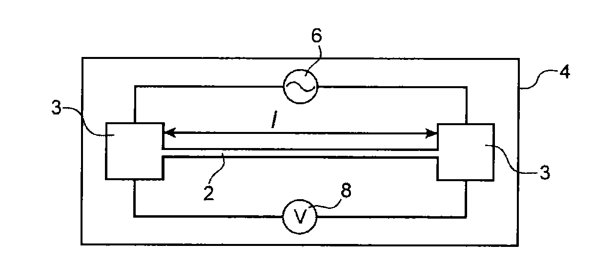
[0048]In FIG. 1, an exemplary measuring device according to the invention can be seen, comprising a suspended element 2 with respect to a support 4 at its two longitudinal ends. The nanowire 2 is anchored to the support by anchoring pads 3 forming contact pads. The suspended element 2 is a nanowire.

[0049]In the description that follows, use is made of the phrase “the terminals of the nanowire”; these are contact pads of the nanowire on the support which are generally formed on the anchoring pads of the nanowire on the support. The element 2 is of an electrically conductive material, for example of a doped or undoped semi-conductor material, for example of N or P doped silicon, TiN, metal or metal alloys or even silicides, for example of NiSi.

[0050]The length of the nanowire is advantageously between 1 μm and 100 μm and the width and thickness of the nanowire are advantageously between 10 nm and 1 μm.

[0051]The measuring device also comprises dynamic or modulated excitation means form...


PUM


Abstract

A thermal flow sensor comprising at least one first element (2) suspended with respect to a support, said first suspended element (2) being of an electrically conductive material, first means (6) for biasing said suspended element (2) and first means (8) for measuring the variation of the electric voltage at the terminals of the suspended element (2), said first suspended element (2) being formed by a nanowire and said first biasing means (6) are formed by an alternating current source the intensity of which provides heating of the first suspended element (2) by Joule effect.

Description

TECHNICAL FIELD AND PRIOR ART[0001]The present invention relates to a thermal flow sensor, which can be intended to measure the concentration of a gas or TCD sensor or to measure very low pressures thus forming a Pirani gauge.[0002]Generally, by thermal flow sensor, it is meant any sensor measuring a heat exchange between the sensor body (membrane) and the fluid medium in which the sensor is disposed.[0003]A thermal flow sensor is placed in an environment containing the element to be analysed, an analyte in a carrier gas in the case of a gas sensor or simply a number of gas molecules in the case of a Pirani gauge.[0004]Document WO2001 / 044547 describes a TCD (“Thermal Conductivity Detectors”) sensor using the variation in the thermal conductivity to determine the composition of the gas environment in which it is disposed. It is disposed at the output of a chromatography column. This TCD sensor comprises an elongate support plate, a heating element located on the support plate. The vo...

Claims


Application Information

Patent Timeline
IPC IPC(8): G01N30/66G01N25/18G01K17/00
CPCG01N27/18G01N30/66G01N2011/0093G01N25/18G01K17/00G01K7/16G01K2211/00G01L21/12G01N33/0004
Inventor RUELLAN, JEREMIEDURAFFOURG, LAURENTARCAMONE, JULIENANDREUCCI, PHILIPPECOLINET, ERIC
Owner COMMISSARIAT A LENERGIE ATOMIQUE ET AUX ENERGIES ALTERNATIVES
Why Eureka
Try Eureka