
Thin Film Transistor, Manufacturing Method Thereof and Thin Film Transistor Array Substrate

a technology of thin film transistors and array substrates, applied in transistors, semiconductor devices, electrical devices, etc., can solve problems such as the chaos of display on achieve the effects of improving the quality of the flat panel display, reducing the effect of light on the device performance, and increasing the stability of the devi

Active Publication Date: 2015-09-03
SHENZHEN CHINA STAR OPTOELECTRONICS TECH CO LTD
View PDF3 Cites 9 Cited by
  • Summary
  • Abstract
  • Description
  • Claims
  • Application Information

AI Technical Summary

Benefits of technology

The present invention provides a thin film transistor with a shielding layer to protect it from external light and increase its stability. Additionally, the thin film transistor uses a heavily doped semiconductor to increase output efficiency. The thin film transistor can also follow existing processes for mass production. These technical effects improve the performance and quality of flat panel displays.

Problems solved by technology

However, when the external light irradiate on the thin film transistor mentioned above, the light will affect the threshold voltage of the TFT, and the changes of the threshold voltage accompanying with bias stress will be accelerated, which will result in the display chaos of flat panel display.

Method used


Image

  • Thin Film Transistor, Manufacturing Method Thereof and Thin Film Transistor Array Substrate
  • Thin Film Transistor, Manufacturing Method Thereof and Thin Film Transistor Array Substrate
  • Thin Film Transistor, Manufacturing Method Thereof and Thin Film Transistor Array Substrate

Examples


Embodiment Construction

[0030]In order to more clearly illustrate the embodiment of the present invention or the technical issue of the prior art, the accompanying drawings and the detailed descriptions are as follows.

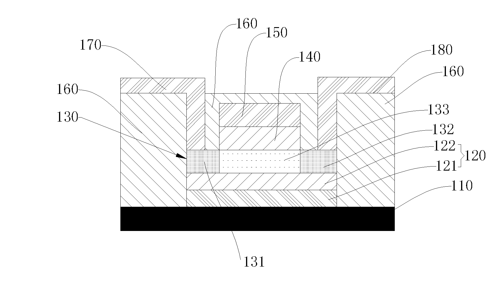
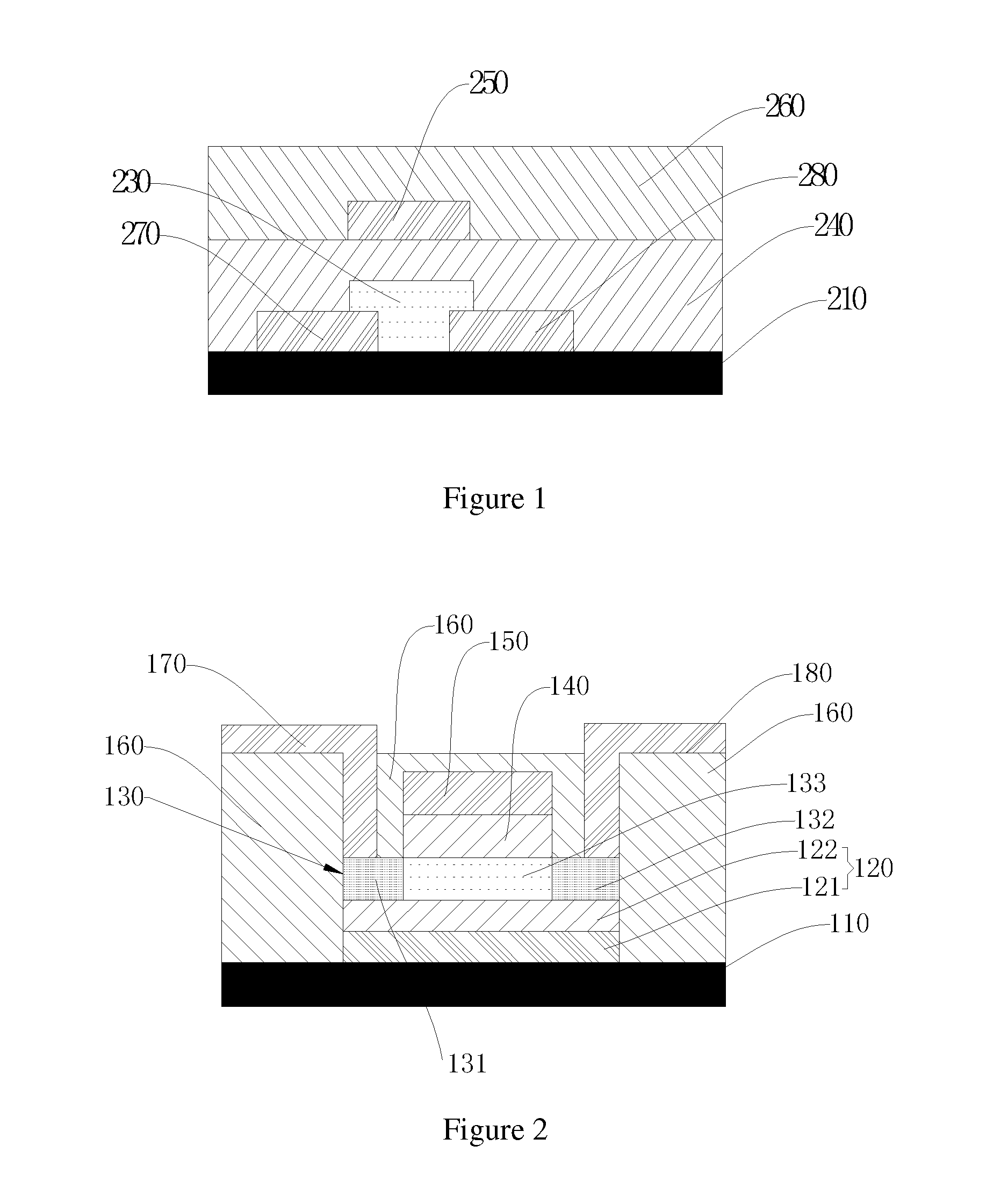
[0031]FIG. 2 is a schematic view illustrating the structure of a thin film transistor according to an embodiment of the present invention.

[0032]Referring to FIG. 2, the thin film transistor according to an embodiment of the present invention comprises a shielding layer 120, an active layer 130, a gate insulating layer 140, a gate electrode 150, a passivation layer 160, a source electrode 170, and a drain electrode 180 formed on a substrate 110.

[0033]Specifically, the shielding layer 120 is deposited on the substrate 110, which is used to absorb external light and then protects the units of the thin film transistor according to the present embodiment. The active layer 130 is a semiconductor layer deposited on the shielding layer 120 as a conductive channel, the material of which is IGZO in the...


PUM


Abstract

The present invention discloses a thin film transistor, comprising an active layer, a gate insulating layer, a gate electrode, a source electrode, and a drain electrode formed on a substrate. The active layer is above the substrate. The gate insulating layer, the source electrode, and the drain electrode are above the active layer. The gate electrode is above the gate insulating layer. Wherein, the thin film transistor further comprises a shielding layer between the substrate and the active layer, the shielding layer is used to absorb external light. The thin film transistor according to the present invention not only has strong stability, but also has high output efficiency. Moreover, the thin film transistor can follow the existing process, which facilitates mass production. The present invention further discloses a manufacturing method of the thin film transistor and a thin film transistor array substrate using the thin film transistor.

Description

BACKGROUND OF THE INVENTION[0001]1. Field of the Invention[0002]The present invention relates to the technology fields of liquid crystal display, and in particular to a thin film transistor, the manufacturing method thereof, a thin film transistor array substrate and a liquid crystal panel.[0003]2. The Related Arts[0004]Thin flat panel display with small body and low power consumption is widely used. The existing thin flat panel display comprises liquid crystal display (LCD) and organic electroluminesence display (OLED).[0005]Liquid crystal display (LCD) is consisted of color or monochrome pixels with a certain amount, which is placed in front of the light source or the reflector. Liquid crystal display has low power consumption, high image quality, small size, and light weight, so it is favored to become the mainstream of display.[0006]Organic electroluminesence display is different from the liquid crystal display. It doesn't need backlight. It is consisted of an organic coating la...

Claims


Application Information

Patent Timeline
Patent Type & Authority Applications(United States)
IPC IPC(8): H01L29/786H01L27/12H01L21/02H01L29/24H01L29/66
CPCH01L29/78633H01L29/7869H01L29/24H01L27/1225H01L29/66969H01L21/02565H01L29/78618
Inventor SU, CHIH-YU
Owner SHENZHEN CHINA STAR OPTOELECTRONICS TECH CO LTD
Learn More